Outer circle chamfering machine tool for numerical control piston ring

A piston ring and chamfering technology, which is applied in the field of CNC machine tools, can solve the problems of low processing efficiency, large processing range, and high efficiency, and achieve the effects of improving production efficiency, reducing tooling operations, and good overall rigidity

Inactive Publication Date: 2017-10-17
NANTONG DEXIN NUMERICAL CONTROL MACHINE TOOL
View PDF8 Cites 2 Cited by
  • Summary
  • Abstract
  • Description
  • Claims
  • Application Information

AI Technical Summary

Problems solved by technology

[0002] In the chamfering process of the outer circle of the piston ring, the piston ring processing equipment is a special machine tool for the internal combustion engine manufacturing industry. At present, most of the piston ring outer circle processing machine tools adopt the manual clamping and processing method of the desktop lathe, which is inefficient and unstable. There is no comprehensive Automatic, multi

Method used


Image

  • Outer circle chamfering machine tool for numerical control piston ring
  • Outer circle chamfering machine tool for numerical control piston ring

Examples


Embodiment Construction

[0013] The present invention will be further described below in conjunction with the accompanying drawings and specific embodiments.

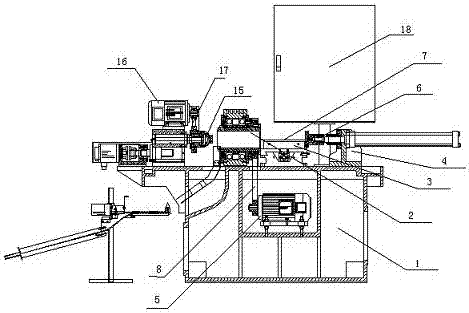
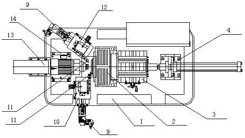
[0014] Such as Figure 1~2 As shown, a numerically controlled piston ring excircle chamfering machine tool disclosed by the present invention includes a machine base 1, a rotating frame 2, a feeding frame 3, a pushing frame 4, a front tool rest mechanism, a rear tool rest mechanism, and positioning Mechanism and rotation synchronous frequency conversion motor 5, wherein the rotating frame 2, the feeding frame 3 and the pushing frame 4 are installed on the upper surface of the machine tool base successively, and the rotating frame 2 is located in the middle, and the pushing frame 4 is positioned at the far right side, the The positioning mechanism is installed on the upper surface of the machine tool base 1 and is positioned at the rear of the rotating frame 2. The front tool rest mechanism is positioned at one side of the positioning mechanism ...


PUM


Abstract

The invention discloses an outer circle chamfering machine tool for a numerical control piston ring. The outer circle chamfering machine tool comprises a machine tool base, a rotary rack, a storing frame, a pushing frame, a front knife rest mechanism, a rear knife rest mechanism, a positioning mechanism and a rotary synchronous variable-frequency motor. The rotary rack, the storing frame and the pushing frame are sequentially installed on the upper surface of the machine tool base, the rotary rack is located in the middle, and the pushing frame is located on the right side; a pushing oil cylinder is installed on the pushing frame, the piston ring on the storing frame is pushed into the rotary rack, and meanwhile, the rotary rack is connected with the rotary synchronous variable-frequency motor installed below the machine tool base through a belt for transmission; the positioning mechanism is installed on the upper surface of the machine tool base and is located right behind the rotary rack; and the front knife rest mechanism is located on one side of the positioning mechanism and is arranged perpendicular to the positioning mechanism, the rear knife rest mechanism is located on the other side of the positioning mechanism, and an included angle of 45 degrees between the rear knife rest mechanism and the positioning mechanism is formed.

Description

technical field [0001] The invention relates to the field of numerically controlled machine tools, in particular to a numerically controlled piston ring outer circle chamfering machine tool. Background technique [0002] In the chamfering process of the outer circle of the piston ring, the piston ring processing equipment is a special machine tool for the internal combustion engine manufacturing industry. At present, most of the piston ring outer circle processing machine tools adopt the manual clamping and processing method of the desktop lathe, which is inefficient and unstable. There is no comprehensive Automatic, multi-functional, and large-scale processing equipment, most of which are remanufactured equipment, many of which are substitutes, fully automatic, poor rigidity, large-bore rings cannot be processed, and small-bore rings cannot be processed automatically. This hydraulic clamping, The precision is controlled by the numerical control system, the rigidity is good,...

Claims


Application Information

Patent Timeline
IPC IPC(8): B23B5/36B23Q7/00
CPCB23B5/365B23Q7/006Y02P70/10
Inventor 顾毅施伟顾德泉
Owner NANTONG DEXIN NUMERICAL CONTROL MACHINE TOOL
Why Eureka
Try Eureka