Automatic tin soldering device

An automatic welding and driving device technology, applied in auxiliary devices, welding equipment, soldering irons, etc., can solve problems such as uneven product performance, low production efficiency, and insufficient stability, so as to save production costs and improve solder quality , Improve the effect of soldering tin quality and soldering efficiency

Active Publication Date: 2017-10-17
WUHU BOKANG ELECTRICAL
View PDF7 Cites 5 Cited by
  • Summary
  • Abstract
  • Description
  • Claims
  • Application Information

AI Technical Summary

Problems solved by technology

[0002] Most of the traditional wire harness winding and soldering processes in the soldering industry are manual, which will lead to low production efficiency, serious waste of raw materials, uneven performance of the produced products, and insufficient stability. Need to make improvements in the soldering process

Method used


Image

  • Automatic tin soldering device

Examples


Embodiment Construction

[0012] In order to make the technical means, creative features, goals and effects achieved by the present invention easy to understand, the present invention will be further described below in conjunction with specific embodiments.

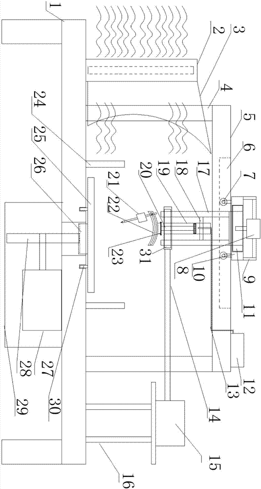
[0013] Such as figure 1 As shown, an automatic soldering device includes an operating table 1 and a driving device, an adjusting device, and a soldering device located on the operating table 1. The operating table 1 is provided with a strip groove and two parallel grooves The slide rail 30, the bottom end of the strip-shaped groove has a through groove communicating with the lower end of the console 1, the solder plate 25 is slidably installed in the slide rail 30, and the lower end surface of the solder plate 25 is provided with parallel The protrusion on the slide rail is welded with a toothed rack 26 facing downwards on the protrusion, and the driving device includes a rotating motor one 27 and a gear 28 installed on the first driving end of th...


PUM


Abstract

The invention discloses an automatic tin soldering device and relates to the technical filed of automation equipment. The automatic tin soldering device comprises an operation table, a driving device, an adjusting device and a tin soldering device, wherein the driving device, the adjusting device and the tin soldering device are located on the operation table. The operation table is provided with a strip-shaped groove and two sliding rails parallel to the strip-shaped groove. A through groove communicating with the lower end of the operation table is formed in the bottom end of the strip-shaped groove. A tin soldering plate is slidably installed in the sliding rails. A bulge parallel to the sliding rails is arranged on the lower end face of the tin soldering plate. A rack with the downward tooth direction is welded to the bulge. The driving device comprises a first rotating motor and a gear installed at the driving end of the rotating motor. The gear is engaged with the rack through the through groove. The tin soldering device comprises an air pump and a tin soldering pen located at the lifting end of the air pump. Complex tin soldering operation can be adjusted step by step, the tin soldering quality and the tin soldering efficiency are improved, and the production cost is reduced.

Description

technical field [0001] The invention relates to the technical field of automation equipment, in particular to an automatic soldering device. Background technique: [0002] Most of the traditional wire harness winding and soldering processes in the soldering industry are manual, which will lead to low production efficiency, serious waste of raw materials, uneven performance of the produced products, and insufficient stability. Improvements are needed in the soldering process. Contents of the invention [0003] The object of the present invention is to provide an automatic soldering device to solve the above-mentioned multiple defects in the prior art. [0004] An automatic soldering device, including an operating table, a driving device, an adjusting device and a soldering device on the operating table, the operating table is provided with a bar-shaped groove and two slide rails parallel to the bar-shaped groove, the The bottom end of the bar-shaped groove is opened with ...

Claims


Application Information

Patent Timeline
Patent Type & Authority Applications(China)
IPC IPC(8): B23K3/00B23K3/08B23K3/02
CPCB23K3/00B23K3/027B23K3/08B23K3/087
Inventor 朱磊马能发李华郑凯邱亮亮施其兵方良周前宽张冲张静冯瑞叶立新张建军杨开文
Owner WUHU BOKANG ELECTRICAL
Why Eureka
Try Eureka