Tin furnace structure for manufacture of power modules

A power module and tin furnace technology, which is applied in the direction of manufacturing tools, auxiliary devices, metal processing, etc., can solve the problems of poor heat insulation effect, human body injury, environmental hazards, etc., achieve good heat preservation effect, avoid pollution, The effect of improving usability

Inactive Publication Date: 2017-11-24
阜阳扬宇充电设备有限公司
View PDF9 Cites 2 Cited by
  • Summary
  • Abstract
  • Description
  • Claims
  • Application Information

AI Technical Summary

Problems solved by technology

[0002] Generally speaking, a tin furnace refers to a welding tool used in electronic welding. The tin furnace plays a very important role in the manufacturing process of the power module. The existing tin furnace has the following problems when performing welding operations: (1) Since the shell of tin furnace is usually made of titanium alloy material, titanium alloy has good high temperature resistance, corrosion resistance and long service life, but its heat insulation effect is poor. , it is necessary to ensure that the inside of the tin furnace reaches a certain temperature, and the temperature has a great influence on the effect of soldering and the performance of the power module after soldering, so it is necessary to install a heat insulation layer outside the shell of the tin furnace; (2) During the soldering process In the process, many harmful organic waste gases will be produced. If these waste gases cannot be treated, they will not only pollute the atmosphere, but also cause harm to human bodies. The existing tin furnace structure does not contain waste gas treatment devices, so it still needs to be developed; (3 ) Existing tin furnaces do not have a tin slag recycling device. After the soldering is completed, the generated tin slag is often discarded directly, which will not only cause a waste of resources, but also bring harm to the environment

Method used


Image

  • Tin furnace structure for manufacture of power modules
  • Tin furnace structure for manufacture of power modules
  • Tin furnace structure for manufacture of power modules

Examples


Embodiment

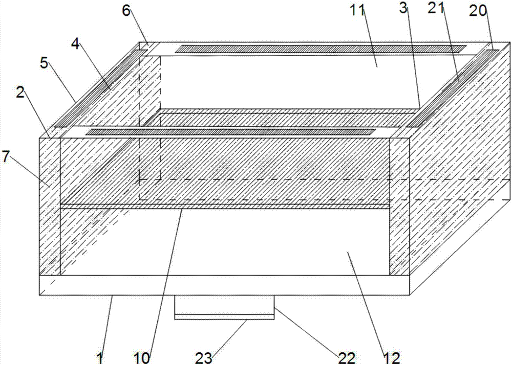
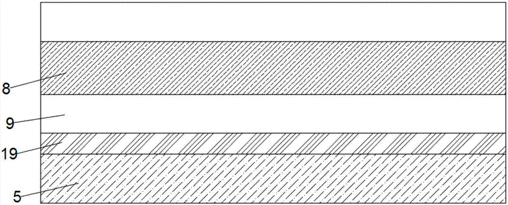
[0024] like Figure 1 to Figure 4 As shown, the present invention provides a tin furnace structure for the manufacture of power modules, including a cuboid furnace body 1, the furnace body 1 includes a shell 2 and an inner cavity 3, and the shell 2 includes an inner layer body 4 and an outer layer body 5, a hollow interlayer 6 is arranged between the inner layer body 4 and the outer layer body 5, and a heat insulation layer 7 is arranged inside the hollow interlayer 6, and the heat insulation layer 7 includes a heat-resistant foamed polymer Ethylene layer 8 and polyurethane fiber non-woven fabric 9, the polyurethane fiber non-woven fabric 9 is arranged on both sides of the heat-resistant foamed polyethylene layer 8, the inner cavity 3 is provided with a horizontal partition 10, the The partition 10 divides the inner cavity 3 into a solder chamber 11 and a tin slag recovery chamber 12. The solder chamber 11 is used for welding the power module to be soldered, and the tin slag r...


PUM


Abstract

The invention discloses a tin furnace structure for manufacture of power modules; the tin furnace structure comprises a furnace body; the furnace body comprises a housing and an inner chamber; the housing comprises an inner layer and an outer layer; a hollow interlayer is arranged between the inner layer and the outer layer; a heat insulation layer is arranged in the hollow interlayer; a partition is arranged in the inner cavity and divides the inner cavity into a soldering tin chamber and a tin residue recovery chamber, the partition is composed of a plurality of support rods, a protective cover is arranged at the top end of the outer layer, the protective cover is composed of four trapezoidal plates identical in shape and size, a suction duct is arranged at the top ends of the four trapezoidal plates, one end of the suction duct is connected with the top ends of the trapezoidal plates, the other end of the suction duct is connected with a suction fan, and the part of the inside of the suction duct close to the top ends of the trapezoidal plates is provided with an activated carbon adsorbing layer and a strainer layer. The tin furnace structure can provide tin soldering for the manufacture of power modules, allows issues provided by the background art to be effectively solved, and is worthy of popularization.

Description

technical field [0001] The invention relates to the technical field of power module manufacturing, in particular to a tin furnace structure for power module manufacturing. Background technique [0002] Generally speaking, a tin furnace refers to a welding tool used in electronic welding. The tin furnace plays a very important role in the manufacturing process of the power module. The existing tin furnace has the following problems when performing welding operations: (1) Since the shell of tin furnace is usually made of titanium alloy material, titanium alloy has good high temperature resistance, corrosion resistance and long service life, but its heat insulation effect is poor. , it is necessary to ensure that the inside of the tin furnace reaches a certain temperature, and the temperature has a great influence on the effect of soldering and the performance of the power module after soldering, so it is necessary to install a heat insulation layer outside the shell of the tin...

Claims


Application Information

Patent Timeline
Patent Type & Authority Applications(China)
IPC IPC(8): B23K3/00B23K3/08
CPCB23K3/00B23K3/08
Inventor 程丽
Owner 阜阳扬宇充电设备有限公司
Why Eureka
Try Eureka