Chip capacitor and method of manufacturing same

a chip capacitor and manufacturing method technology, applied in the field of chip capacitors, can solve the problems of relative high cost of materials, failure of soldering, and inability to perform soldering, so as to reduce the number of steps of manufacturing the mount portion, improve the resistance of the chip capacitor to vibration, and reduce the cost of the chip capacitor.

Inactive Publication Date: 2012-06-28
SAN DENSHI INDS
View PDF6 Cites 2 Cited by
  • Summary
  • Abstract
  • Description
  • Claims
  • Application Information

AI Technical Summary

Benefits of technology

[0035]According to the present invention, the mount portion including the board mounting surface is formed of the resin containing the organic metal complex compound, and the assistant terminal portion is formed by plating the region to which the metal is exposed by applying laser light onto the board mounting surface. It is therefore possible not only to improve the resistance of the chip capacitor to vibrations by soldering the assistant terminal portion to the circuit board but also to reduce the cost of the chip capacitor by reducing the number of steps of manufacturing the mount portion. Furthermore, the coplanarity can be enhanced, and thus it is possible to enhance the quality of the soldering of the chip capacitor.

Problems solved by technology

However, in the capacitor in which the assistant terminal portion is formed by insert molding, as the material of the metal plate 22, a relatively expensive material, for example, a brass base material that is plated with tin or the like is used.
Thus, when cream solder is applied to the circuit board to mount the capacitor 1 on the surface of the board, the capacitor 1 may be inclined, and, when a smaller amount of cream solder is applied, a failure may occur in soldering.
Moreover, when the amount of protrusion D is negative due to the wear of a die or the like, and hence the assistant terminal portion 21 is recessed with respect to the board mounting surface 20a, a fatal failure occurs in which it is impossible to perform soldering.
Consequently, when the assistant terminal portion 21 is formed by insert molding, the cost of the capacitor 1 is disadvantageously increased.
Furthermore, since a heat-resistant resin used as the material of the seat plate generally has a high resistance to chemicals and a high mechanical strength, it is almost impossible to rough the surface or it is inefficient to rough the surface.
Consequnetly, when the assistant terminal portion is formed by plating, the cost of the capacitor is likewise increased disadvantageously.

Method used


Image

  • Chip capacitor and method of manufacturing same
  • Chip capacitor and method of manufacturing same
  • Chip capacitor and method of manufacturing same

Examples


Embodiment Construction

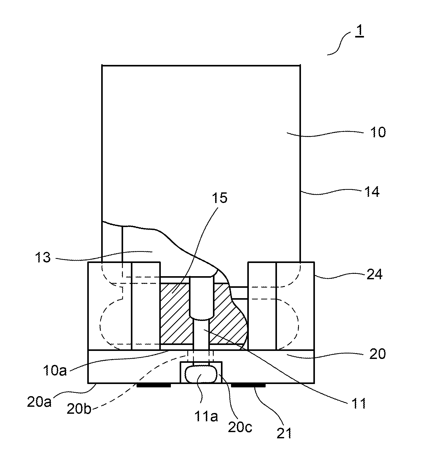
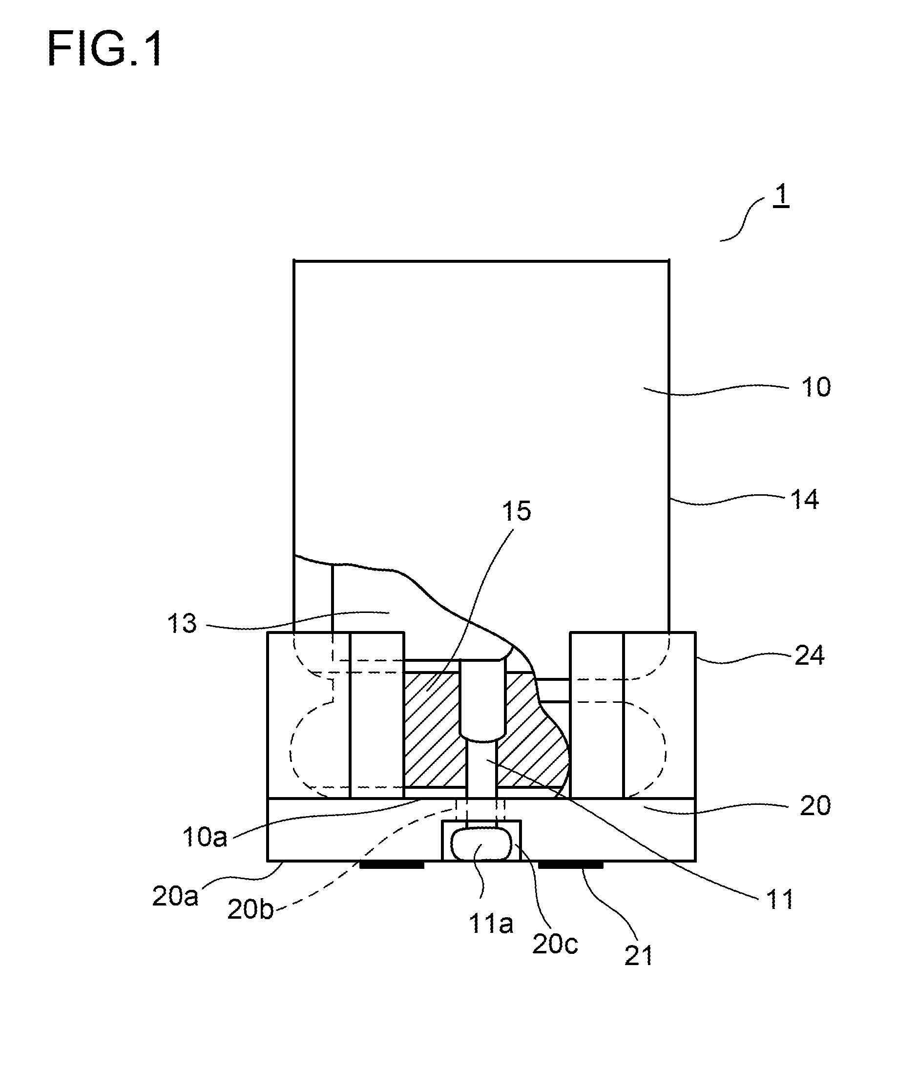
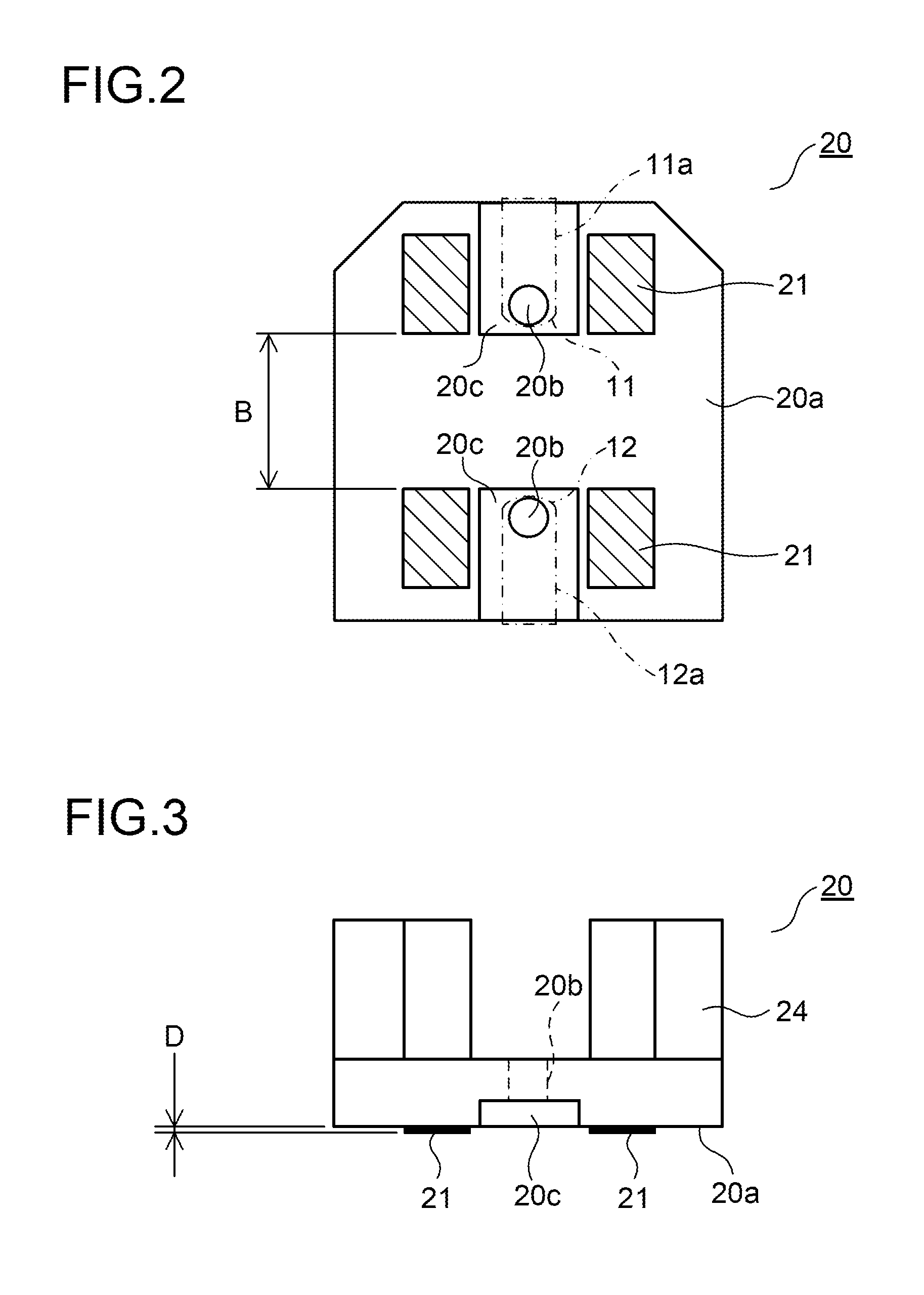
[0052]Embodiments of the present invention will be described below with reference to the accompanying drawings. For convenience of description, the same parts as in the conventional example shown in FIGS. 12 to 16 are identified with common reference numerals. FIGS. 1 and 2 show a front view and a bottom view of a chip capacitor according to a first embodiment, respectively. The capacitor 1 includes a capacitor body 10 and a seat plate 20.

[0053]In the capacitor body 10, a capacitor element 13 is accommodated within a cylindrical metal case 14 with a bottom, and the opening end of the metal case 14 is sealed with a sealing member 15 such as rubber. The capacitor element 13 is formed by winding an anode foil and a cathode foil (both of which are unillustrated) through a separator (unillustrated) such as capacitor paper. The anode foil is formed with a metal functioning as a valve, such as aluminum, tantalum, niobium or titanium; a dielectric coating is formed on the surface of the ano...


PUM

PropertyMeasurementUnit
heat distortion temperatureaaaaaaaaaa
temperaturesaaaaaaaaaa
temperatureaaaaaaaaaa

Abstract

A chip capacitor (1) includes: a capacitor body (10) from which an anode lead wire (11) and a cathode lead wire (12) are extended out; and a mount portion (20) which is fitted to the capacitor body (10), in which terminal portions (11a and 12a) of the lead wires (11 and 12) are arranged in a board mounting surface (20a) and which is placed on a circuit board. In the chip capacitor (1) in which the terminal portions (11a and 12a) are soldered to the circuit board, the mount portion (20) is formed of a resin containing an organic metal complex compound, and an assistant terminal portion (21) formed by plating a region to which a metal is exposed by applying laser light onto the board mounting surface (20a) is provided.

Description

[0001]This application is based on Japanese Patent Application No. 2010-288402 filed on Dec. 24, 2010, the contents of which are hereby incorporated by reference.BACKGROUND OF THE INVENTION[0002]1. Field of the Invention[0003]The present invention relates to a chip capacitor that is mounted on the surface of a board and a method of manufacturing such a chip capacitor.[0004]2. Description of Related Art[0005]FIGS. 12 and 13 show a front view and a bottom view of a conventional chip capacitor, respectively. The capacitor 1 includes a capacitor body 10 and a seat plate 20. In the capacitor body 10, an anode lead wire 11 and a cathode lead wire 12 are extended out from an exit surface 10a that is one end surface.[0006]The seat plate 20 is formed with a molded resin product; one surface thereof comes in contact with the exit surface 10a of the capacitor body 10, and the other surface forms a board mounting surface 20a that is placed on a circuit board. In the seat plate 20, there are pro...

Claims


Application Information

Patent Timeline
Patent Type & Authority Applications(United States)
IPC IPC(8): H01G4/228H05K3/30
CPCH01G2/065H01G9/012Y10T29/4913H05K3/3436H05K2201/10015H01G9/10
Inventor TAKETANI, YUTAKAYOSHIZAWA, HITOSHITERAJI, KAZUOSAIKI, NAOYA
Owner SAN DENSHI INDS
Why Eureka
Try Eureka