Surface-coated cutting tool and method for manufacturing same

A cutting tool and surface coating technology, applied in the field of surface coating cutting tools, can solve problems such as insufficient wear resistance, and achieve the effect of improving wear resistance and chipping resistance

Active Publication Date: 2013-01-02
SUMITOMO ELECTRIC HARDMETAL CORP
View PDF5 Cites 13 Cited by
  • Summary
  • Abstract
  • Description
  • Claims
  • Application Information

AI Technical Summary

Problems solved by technology

[0011] On the other hand, as disclosed in Patent Document 2, although the chipping resistance is reliably improved by providing a specific inclination angle distribution with respect to the crystal plane of the crystal grains of the TiCN layer, the coating film itself cannot be highly hardened, and as a result Yes, insufficient wear resistance when the tool is used for continuous cutting etc.

Method used


Image

  • Surface-coated cutting tool and method for manufacturing same
  • Surface-coated cutting tool and method for manufacturing same
  • Surface-coated cutting tool and method for manufacturing same

Examples


Embodiment

[0071] Hereinafter, the present invention will be described in more detail with reference to Examples, but the present invention is not limited thereto.

[0072]

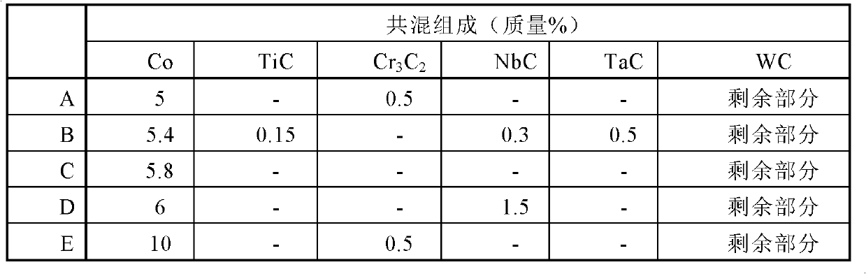
[0073] Five types of substrates A to E shown in Table 1 below were prepared. Specifically, raw material powders having the blending composition shown in Table 1 were uniformly mixed and molded into a predetermined shape, and then sintered at 1300° C. to 1500° C. for 1 to 2 hours, thereby forming a cemented carbide A substrate (manufactured by Sumitomo Electric Hardmetal Corp.) constituted and shaped as CNMG120408N-GZ.

[0074] [Table 1]

[0075]

[0076]

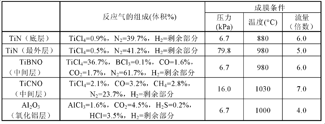
[0077] A coating film was formed on the surface of the substrate prepared as described above. Specifically, the base material is placed in a chemical vapor deposition device (the volume of the reaction chamber: 0.27m 3 ), a coating film is formed on the substrate by a chemical vapor deposition method. The conditions for forming the coating film are as d...


PUM

PropertyMeasurementUnit
thicknessaaaaaaaaaa
thicknessaaaaaaaaaa
thicknessaaaaaaaaaa

Abstract

This surface-coated cutting tool is characterized in that the tool includes a base material, and a film formed on the base material, the film includes at least one TiCN layer, the TiCN layer has a column crystal region, the column crystal region has a composition represented by the formula TiCxNy (0.65=x / (x+y)=0.90), a lattice spacing of (422) planes is 0.8765-0.8790 AA, and that an index (TC(220)) is highest in orientation index (TC (hkl)).

Description

technical field [0001] The present invention relates to a surface-coated cutting tool including a base material and a coating film formed on the base material and a method of manufacturing the surface-coated cutting tool. Background technique [0002] Conventionally, there is a known surface-coated cutting tool including a base material and a coating film formed on the base material, in which a TiCN layer is included as the coating film. [0003] For example, Japanese Patent Laid-Open No. 2008-087150 (Patent Document 1) proposes an attempt to improve wear resistance by setting the atomic ratio of carbon to the total of carbon and nitrogen at 0.70 to 0.90 as the composition of the TiCN layer. and crack resistance. [0004] In addition, Japanese Patent Laid-Open No. 2006-231433 (Patent Document 2) proposes an attempt to improve chipping resistance by providing a specific inclination angle distribution with respect to crystal planes of crystal grains of a TiCN layer. [0005]...

Claims


Application Information

Patent Timeline
Patent Type & Authority Applications(China)
IPC IPC(8): B23B27/14B23B51/00B23C5/16C23C16/36
CPCC23C16/0272C23C28/042C23C16/52B23B51/00C23C28/044B23C5/16C23C16/36C23C30/005B23B27/14C23C16/30
Inventor 阿侬萨克·帕索斯冈田吉生小岛周子金冈秀明岩井惠里香森本浩之
Owner SUMITOMO ELECTRIC HARDMETAL CORP
Why Eureka
Try Eureka