Cutting tool

A cutting tool, hard phase technology, used in the manufacture of tools, workpieces, turning equipment, etc., can solve problems such as limitations, different sizes, and difficulty in obtaining toughness

Active Publication Date: 2013-09-04
KYOCERA CORP
View PDF5 Cites 14 Cited by
  • Summary
  • Abstract
  • Description
  • Claims
  • Application Information

AI Technical Summary

Problems solved by technology

[0011] However, in the method of generating residual stress in a cermet sintered body due to a difference in the content of the binder phase between the surface and the inside as in the above-mentioned Patent Document 1, since the content ratio of the binder phase in the entire cermet is relatively small Small, not enough residual stress is applied relative to the overall cermet, and it is difficult to obtain satisfactory toughness
[0012] In addition, even in the method of uniformly applying residual stress to the hard phase as in Patent Document 2, there is a limit in improving the strength of the hard phase.
[0013] In addition, in the structure of the above-mentioned Patent Document 3, the fracture resistance of the cermet as a cutting tool is improved, but the cermet tends to have a larger amount of deformation caused by firing than the cemented carbide. When cutting tools with complex shapes with corner blades (Japanese: コナナ一刀刀), there are problems such as the position and shape of the corner blades are different depending on the angle used, and the dimensions during cutting are different.

Method used


Image

  • Cutting tool
  • Cutting tool
  • Cutting tool

Examples


Embodiment

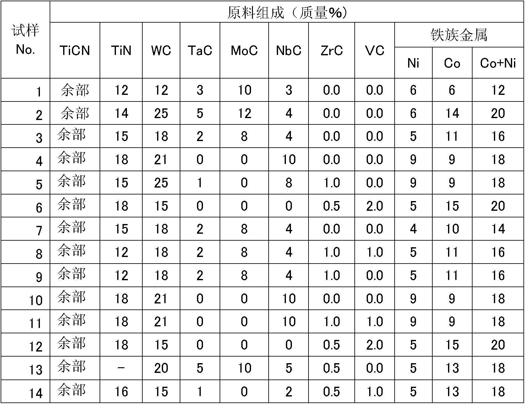
[0066] In the measurement of laser particle size (Japanese: Microtrac) method, the average particle diameter (d 50 value) TiCN powder with an average particle diameter of 1.1 μm, WC powder with an average particle diameter of 1.1 μm, TiN powder with an average particle diameter of 1.5 μm, VC powder with an average particle diameter of 1.0 μm, TaC powder with an average particle diameter of 2 μm, and MoC powder with an average particle diameter of 1.5 μm powder, NbC powder with an average particle diameter of 1.5 μm, ZrC powder with an average particle diameter of 1.8 μm, Ni powder with an average particle diameter of 2.4 μm, Co powder with an average particle diameter of 1.9 μm, and MnCO powder with an average particle diameter of 5.0 μm 3 The powders were adjusted in the ratio shown in Table 1 to form a mixed powder, which was wet-mixed by adding isopropyl alcohol (IPA) using a stainless steel ball mill and superhard balls, and mixed by adding 3% by mass of paraffin wax. Then...


PUM

PropertyMeasurementUnit
compressive stressaaaaaaaaaa
diameteraaaaaaaaaa

Abstract

[Problem] To provide a cutting tool which is formed from a cermet sintered body that is reduced in deformation due to firing and has high strength. A cutting tool (1) which is composed of a cermet sintered body (6) that is configured of a hard phase (11) which is composed of two kinds of hard phases, namely a first hard phase (12) and a second hard phase (13), and a binder phase (14) that is composed of Co and / or Ni. At a depth of 400 [mu]m or more from the rake face (2)-side surface of the cermet sintered body (6), the residual stress sigma11[1i] in the s11 direction of the first hard phase (12) is a compressive stress of 80 MPa or more (sigma11[1i] = -80 MPa), the residual stress s11[2i] in the s11 direction of the second hard phase (13) is a compressive or tensile stress of from -50 MPa to 50 MPa (sigma11[2i] = -50 MPa to 50 MPa), and the residual stress sigma11[bi] in the s11 direction of the binder phase (14) is a compressive or tensile stress of from -50 MPa to 50 MPa (sigma11[bi] = -50 MPa to 50 MPa) as determined by a 2D method.

Description

technical field [0001] The present invention relates to a cutting tool composed of a cermet sintered body. Background technique [0002] For example, in Patent Document 1, it is disclosed that by reducing the concentration of the binder phase (iron group metal) in the surface portion of TiC-based cermet containing nitrogen compared with the inside, the existence of the hard phase in the surface portion The ratio is relatively large, so that 30kgf / mm remains on the surface of the sintered body 2 The above compressive residual stress improves wear resistance, chipping resistance, and thermal shock resistance. [0003] Furthermore, in Patent Document 2, it is disclosed that WC grains, which are the main crystals of WC-based cemented carbide, have 120 kgf / mm 2 The above compressive residual stress makes the WC-based superhard alloy have higher strength and excellent fracture resistance. [0004] In addition, in Patent Document 3, it is described that by applying residual stre...

Claims


Application Information

Patent Timeline
Patent Type & Authority Applications(China)
IPC IPC(8): B23B27/14C22C1/05C22C29/02
CPCB22F2005/001C22C1/051C22C29/02Y10T407/27B23B27/14C22C1/05C22C29/16B23B27/148B23B2222/16
Inventor 德永隆司木下秀吉
Owner KYOCERA CORP
Why Eureka
Try Eureka