

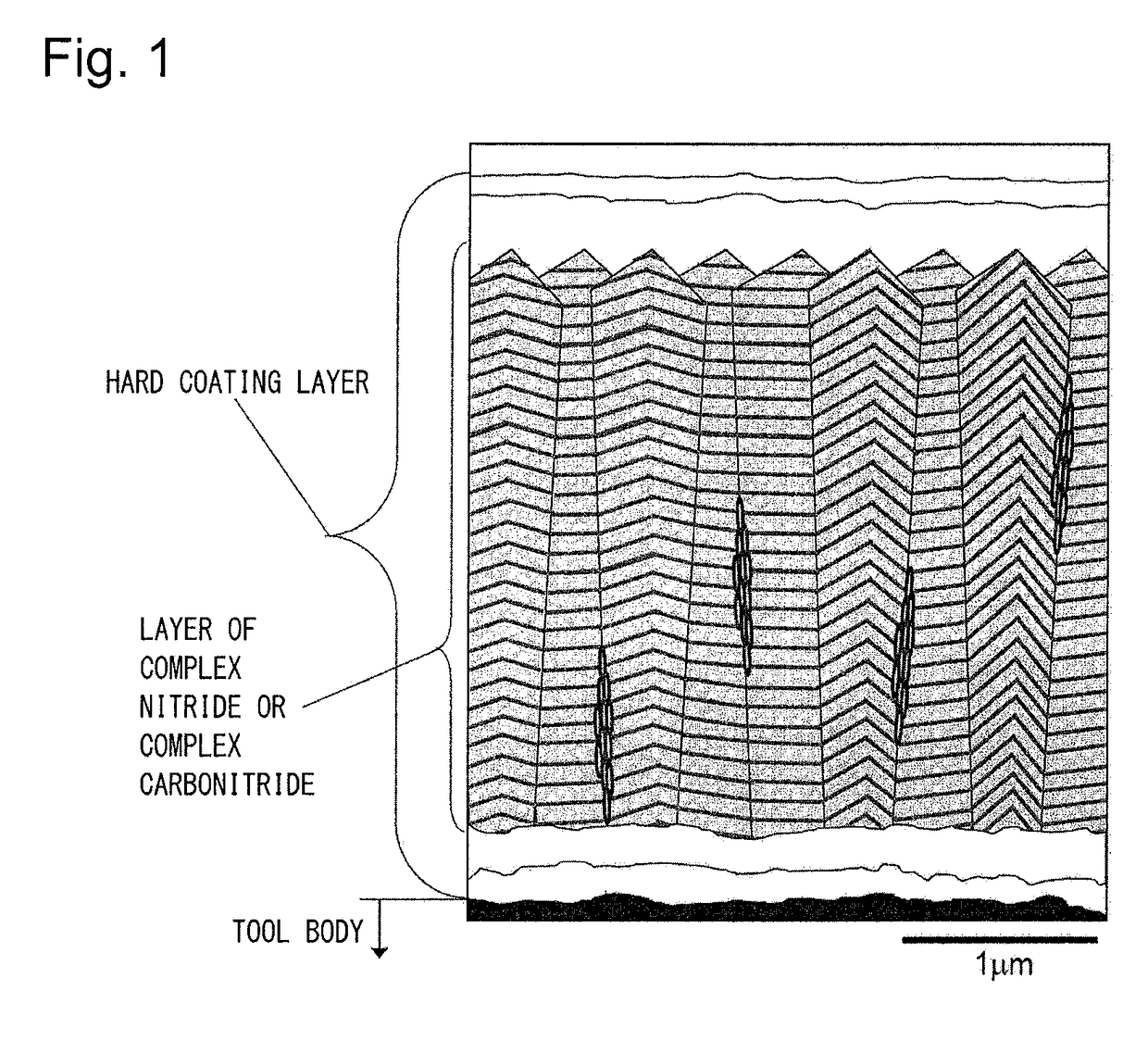
Surface-coated cutting tool in which hard coating layer exhibits excellent chipping resistance
a cutting tool and hard coating technology, applied in the direction of manufacturing tools, turning machine accessories, superimposed coating process, etc., can solve the problems of easy chipping and abnormal wear, and achieve the effects of improving toughness, high wear resistance, and improving hardness of grains
- Summary
- Abstract
- Description
- Claims
- Application Information
AI Technical Summary
Benefits of technology
Problems solved by technology
Method used
Image

Examples
example 1
[0060]As raw material powders, a WC powder, a TiC powder, a TaC powder, an NbC powder, a Cr3C2 powder, and a Co powder, all of which had an average grain size of 1 μm to 3 μm, were prepared, and the raw material powders were mixed in mixing compositions shown in Table 1. Wax was further added thereto, and the mixture was blended in acetone by a ball mill for 24 hours and was decompressed and dried. Thereafter, the resultant was press-formed into compacts having predetermined shapes at a pressure of 98 MPa, and the compacts were sintered in a vacuum at 5 Pa under the condition that the compacts were held at a predetermined temperature in a range of 1370° C. to 1470° C. for one hour. After the sintering, tool bodies A to C made of WC-based cemented carbide with insert shapes according to ISO standard SEEN1203AFSN were produced.
[0061]In addition, as raw material powders, a TiCN (TiC / TiN=50 / 50 in terms of mass ratio) powder, an Mo2C powder, a ZrC powder, an NbC powder, a WC powder, a Co...
example 2
[0091]As raw material powders, a WC powder, a TiC powder, a ZrC powder, a TaC powder, an NbC powder, a Cr3C2 powder, a TiN powder, and a Co powder, all of which had an average grain size of 1 μm to 3 μm, were prepared, and the raw material powders were mixed in mixing compositions shown in Table 10. Wax was further added thereto, and the mixture was blended in acetone by a ball mill for 24 hours and was decompressed and dried. Thereafter, the resultant was press-formed into compacts having predetermined shapes at a pressure of 98 MPa, and the compacts were sintered in a vacuum at 5 Pa under the condition that the compacts were held at a predetermined temperature in a range of 1370° C. to 1470° C. for one hour. After the sintering, a cutting edge portion was subjected to honing to have a radius R of 0.07 mm, thereby forming tool bodies α to γ made of WC-based cemented carbide with insert shapes according to ISO standard CNMG120412.
[0092]In addition, as raw material powders, a TiCN (T...
example 3
[0121]As raw material powders, a cBN powder, a TiN powder, a TiC powder, an Al powder, and an Al2O3 powder, all of which had an average grain size of 0.5 μm to 4 μm, were prepared, and the raw material powders were mixed in mixing compositions shown in Table 16. The mixture was wet-blended by a ball mill for 80 hours and was dried. Thereafter, the resultant was press-formed into compacts having dimensions with a diameter of 50 mm and a thickness of 1.5 mm at a pressure of 120 MPa, and the compacts were then sintered in a vacuum at a pressure of 1 Pa under the condition that the compacts were held at a predetermined temperature in a range of 900° C. to 1300° C. for 60 minutes, thereby producing cutting edge preliminary sintered bodies. In a state in which the preliminary sintered body was superimposed on a support piece made of WC-based cemented carbide, which was additionally prepared to contain Co: 8 mass % and WC: the remainder and have dimensions with a diameter of 50 mm and a th...
PUM
| Property | Measurement | Unit |
|---|---|---|
| thickness | aaaaa | aaaaa |
| average grain width | aaaaa | aaaaa |
| thickness | aaaaa | aaaaa |
Abstract
Description
Claims
Application Information