
Concrete stirring equipment

A mixing equipment and concrete technology, which is applied in the direction of clay preparation equipment, cement mixing equipment, chemical instruments and methods, etc., can solve the problems of affecting the service life of equipment, low equipment working efficiency, and long mixing and mixing time, and achieve convenient mixing and mixing. Effect of improving mixing efficiency and reducing noise pollution

Inactive Publication Date: 2017-10-17
陈仲义
View PDF0 Cites 17 Cited by
  • Summary
  • Abstract
  • Description
  • Claims
  • Application Information

AI Technical Summary

Problems solved by technology

[0004] In the process of building construction and bridge construction, a large amount of concrete is often required for construction, but the existing concrete mixing equipment is generally firstly mixed manually, and then directly put into the concrete after adding water to mix the concrete. Direct mixing in the mixing tank not only wastes manpower and material resources, but also for the uniform mixing of concrete, which often leads to low working efficiency of the equipment, long mixing and mixing time, and it is very inconvenient to unload the equipment after mixing. The equipment will generate a lot of shaking, which will seriously affect the service life of the equipment

Method used


Image

  • Concrete stirring equipment
  • Concrete stirring equipment
  • Concrete stirring equipment

Examples


Embodiment Construction

[0018] It should be noted that, in the case of no conflict, the embodiments of the present invention and the features in the embodiments can be combined with each other.

[0019] In describing the present invention, it should be understood that the terms "center", "longitudinal", "transverse", "upper", "lower", "front", "rear", "left", "right", " The orientations or positional relationships indicated by "vertical", "horizontal", "top", "bottom", "inner" and "outer" are based on the orientations or positional relationships shown in the drawings, and are only for the convenience of describing the present invention and Simplified descriptions, rather than indicating or implying that the device or element referred to must have a particular orientation, be constructed and operate in a particular orientation, and thus should not be construed as limiting the invention. In addition, the terms "first", "second", etc. are used for descriptive purposes only, and should not be understood ...


PUM


Abstract

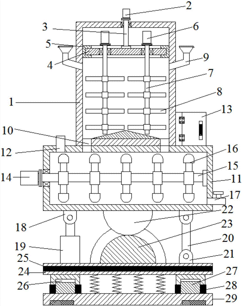
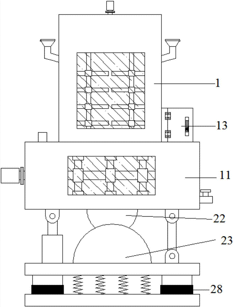
The invention discloses concrete stirring equipment comprising a mixing box. Feeding ports are formed in the upper ends of the left side and the right sides of the mixing box; a stirring box is arranged on the lower side of the mixing box; a water adding pipe is arranged at the left end of the upper side of the stirring box; an electric control box is arranged at the right end of the upper side of the stirring box; a discharging pipe is arranged at the lower end of the right side of the stirring box; first mounting seats are arranged at the four corners of the lower side of the stirring box; a telescopic rod is arranged on the lower side of the first mounting seat at the left end; a connecting rod is arranged on the lower side of the first mounting seat at the right end; a second mounting seat is arranged on the lower side of the connecting rod; a connecting semicircle plate is arranged in the middle of the lower side of the stirring box; a connecting semicircle groove is formed in the lower side of the connecting semicircle plate; and a supporting plate is arranged on the lower sides of the connecting semicircle groove, the telescopic rod and the second mounting seat. A damping pad is arranged inside the supporting plate; linkage notches are formed in the four corners of the lower side of the supporting plate; connecting blocks are arranged on the lower sides inside the linkage notches; damping rings are arranged on the outer sides of the connecting blocks; and a bottom plate is arranged on the lower sides of the connecting blocks. According to the concrete stirring equipment, the working efficiency of the equipment can be effectively improved, unloading is facilitated, and the equipment is effectively protected.

Description

technical field [0001] The invention relates to concrete equipment, in particular to concrete mixing equipment. Background technique [0002] Concrete refers to a mixture made of cement (organic, inorganic or organic-inorganic composite), granular aggregates, water, chemical admixtures and mineral admixtures that need to be added in appropriate proportions, or After hardening, a composite material with a stacked structure is formed (usually cementitious material, water, fine aggregate, coarse aggregate, when necessary, admixtures and mineral admixtures are mixed in an appropriate proportion. [0003] Concrete is a living building material. With the continuous development of concrete composition materials, people's understanding of material composite technology has been continuously improved. The performance requirements of concrete are not limited to compressive strength, but on the basis of strength, more attention is paid to the balance and coordination of comprehensive ...

Claims


Application Information

Patent Timeline
Patent Type & Authority Applications(China)
IPC IPC(8): B28C5/08
CPCB28C5/0875B28C5/0806
Inventor 陈仲义
Owner 陈仲义
Learn More