
Winch steel wire rope tension control device

A technology of tension control and steel wire rope, which is applied in hoisting devices, spring mechanisms, etc., can solve the problems of affecting work efficiency, poor continuity of monitoring timeliness, and low reliability, and achieves a strong practical effect

Inactive Publication Date: 2017-10-17
CHINA FIRST METALLURGICAL GROUP
View PDF4 Cites 3 Cited by
  • Summary
  • Abstract
  • Description
  • Claims
  • Application Information

AI Technical Summary

Problems solved by technology

[0002] When the crane winches and releases the rope (the hook falls), the weight of the empty hook is not large enough, the wire rope magnification of the hook is large, the resistance of each pulley and other factors cause the falling to be unsmooth; at this time, if the operator does not pay attention to reduce the Slow hoisting and unwinding speed, the speed of hoisting and unwinding rope is faster than the requirement of the hook falling, the hoisting rope will be loose, causing hoisting disorder, and even the wire rope jumping out of the hoisting will cause damage to the wire rope
Because the damage of the wire rope directly affects the safety of on-site construction, replacing the wire rope will waste time and affect the construction period, which will directly bring economic losses and affect work efficiency. In the prior art, the control of the speed of the wire rope unwinding mainly depends on the manual monitoring of the driver. On the construction site, manual naked eye monitoring is prone to monitoring dead angles, and the monitoring timeliness is poor in continuity and reliability. Therefore, it is necessary to design a device that can monitor the tightness of the hoisting wire rope in real time.

Method used


Image

  • Winch steel wire rope tension control device
  • Winch steel wire rope tension control device

Examples


Embodiment Construction

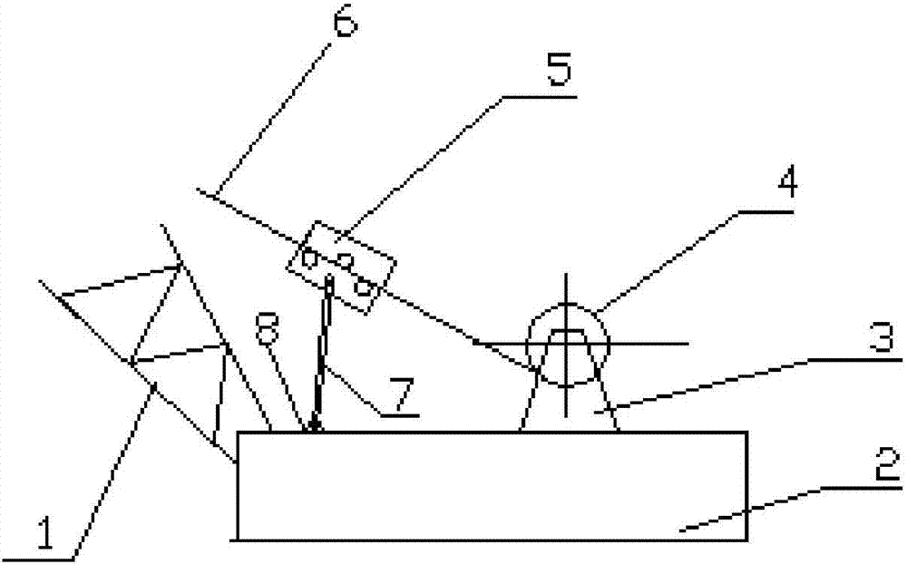
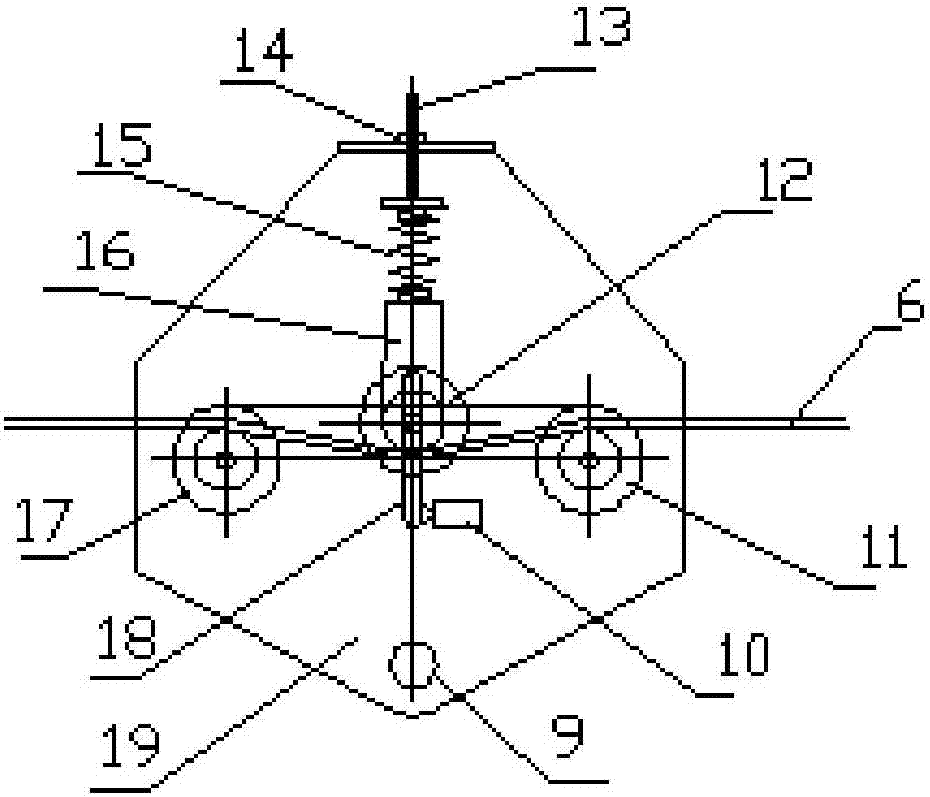
[0015] Below by embodiment, in conjunction with accompanying drawing, the technical scheme of the present invention is described further specifically, as Figure 1-2 As shown, a hoisting steel wire rope tension control device includes a tie rod 7 installed on the machine platform 2 through a tie rod bracket 8 close to the direction of the hoist 4 rope on the machine platform, and the hoist 4 is fixed on the machine platform 2 through the The hoisting bracket 3 is arranged on the machine platform 2, the upper end of the tie rod 7 is provided with a three-pulley assembly 5, and the steel wire rope 6 is connected with the pulley at the upper end of the boom tail section 1 after passing through the three-pulley assembly 5, and is characterized in that: The three pulley assembly 5 includes two front and rear symmetrical installation side plates 19, and three pulleys are arranged between the installation side plates 19, wherein the left pulley 11 and the right pulley 17 are fixed sym...


PUM


Abstract

The invention provides a hoisting steel wire rope tension control device, which comprises a tie rod (7) installed on the machine platform (2) through a tie rod bracket (8) close to the direction of the hoist (4) on the machine platform. The upper end of the rod (7) is provided with a three-pulley assembly (5), and the three-pulley assembly (5) includes two installation side plates (19) symmetrically arranged front and back, and the installation side plates (19) are arranged between There are three pulleys, wherein the left pulley (11) and the right pulley (17) are symmetrically fixed on the installation side plate (19), and the middle pressure roller (12) is movably installed between the two side plates. By setting this device on the machine table close to the end of the hoisting rope, the tightness of the hoisting can be monitored at the end of the hoisting rope. Once the tension of the wire rope is insufficient, the travel switch can be passed in time to control the suspension of the hoisting and stop the rope. Prevent the occurrence of accidents that cause damage to the steel wire rope after hoisting and skipping the rope.

Description

technical field [0001] The invention belongs to the technical field of hoisting machinery construction engineering, and in particular relates to a hoisting wire rope tension control device. Background technique [0002] When the crane winches and releases the rope (the hook falls), the weight of the empty hook is not large enough, the wire rope magnification of the hook is large, the resistance of each pulley and other factors cause the falling to be unsmooth; at this time, if the operator does not pay attention to reduce the Slow hoisting and unwinding speed, the speed of hoisting and unwinding rope is faster than the requirement of the hook falling, the hoisting out rope will be loose, causing hoisting disorder, and even the wire rope jumping out of the hoisting will cause damage to the wire rope. Because the damage of the wire rope directly affects the safety of on-site construction, replacing the wire rope will waste time and affect the construction period, which will di...

Claims


Application Information

Patent Timeline
IPC IPC(8): B66D1/50B66D1/395B66D1/54
CPCB66D1/50B66D1/36B66D1/54
Inventor 董武郭继舟李少祥
Owner CHINA FIRST METALLURGICAL GROUP
Learn More