
Image restoration method and apparatus, and three-dimensional reconstruction system

A technology of three-dimensional reconstruction and camera device, applied in the field of image processing, can solve the problems of affecting the three-dimensional reconstruction result of the measured object, inaccurate information collected by the camera, etc., and achieve the effect of accurate three-dimensional reconstruction results, simple operation, and realization of error areas.

Active Publication Date: 2017-10-17
SICHUAN UNIV
View PDF3 Cites 5 Cited by
  • Summary
  • Abstract
  • Description
  • Claims
  • Application Information

AI Technical Summary

Problems solved by technology

The multi-path effect will lead to inaccurate information collected by the camera, thus affecting the 3D reconstruction results of the measured object

Method used


Image

  • Image restoration method and apparatus, and three-dimensional reconstruction system
  • Image restoration method and apparatus, and three-dimensional reconstruction system
  • Image restoration method and apparatus, and three-dimensional reconstruction system

Examples


no. 1 example

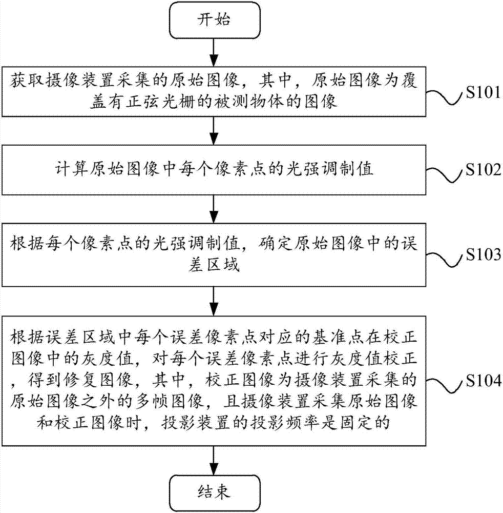
[0039] Please refer to image 3 , image 3 A flowchart of an image restoration method provided by an embodiment of the present invention is shown. The image restoration method includes the following steps:

[0040] Step S101, acquiring an original image collected by a camera device, wherein the original image is an image of a measured object covered with a sinusoidal grating.

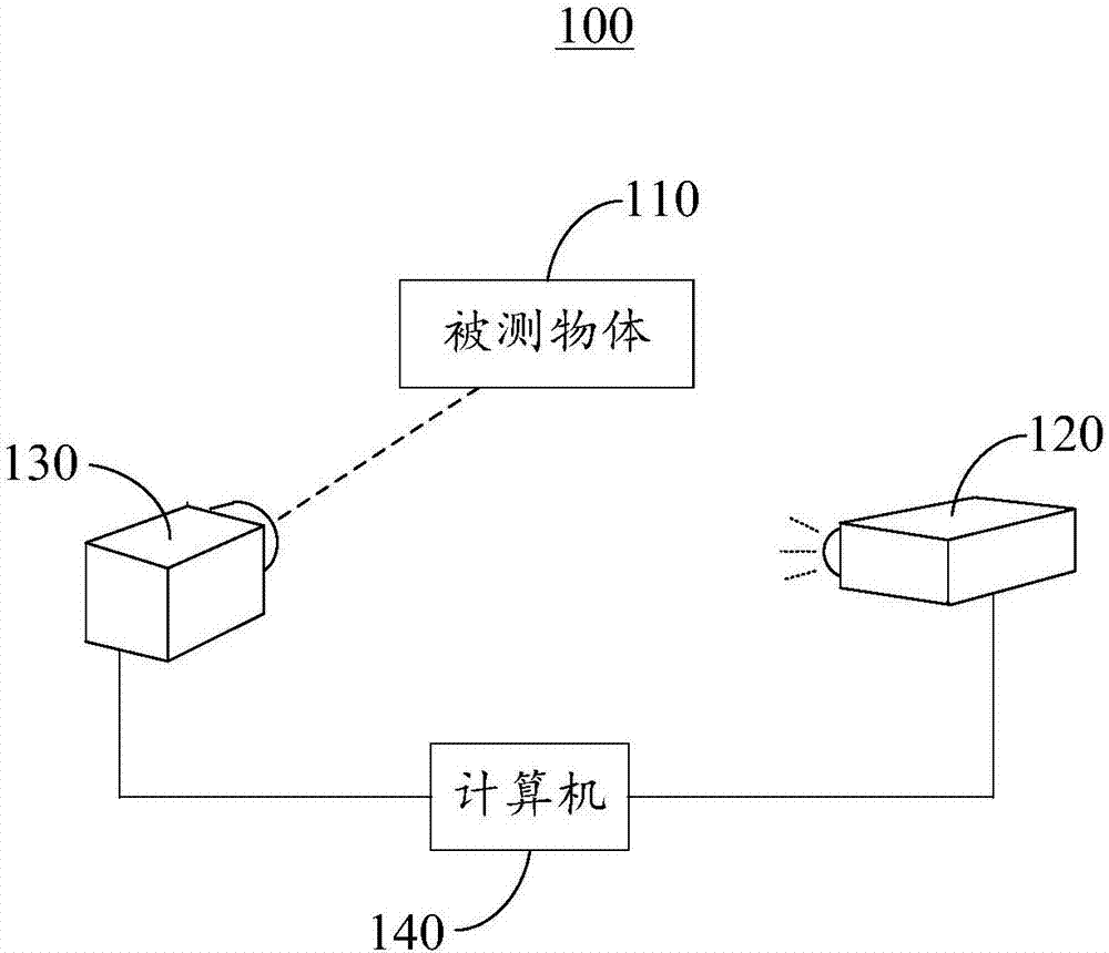
[0041] In the embodiment of the present invention, the projection device 120 projects the sinusoidal grating onto the measured object 110, and the original image may be an image of the measured object 110 collected by the camera device 130 when the measured object 110 is covered with a sinusoidal grating, the sinusoidal grating It may be a coding pattern projected onto the measured object 110 by the projection device 120 . The multipath effect is generated in the sampling process of the camera 130, and the result of the sampling is the original image, while the actual pixel gray value of the camera 1...

no. 2 example

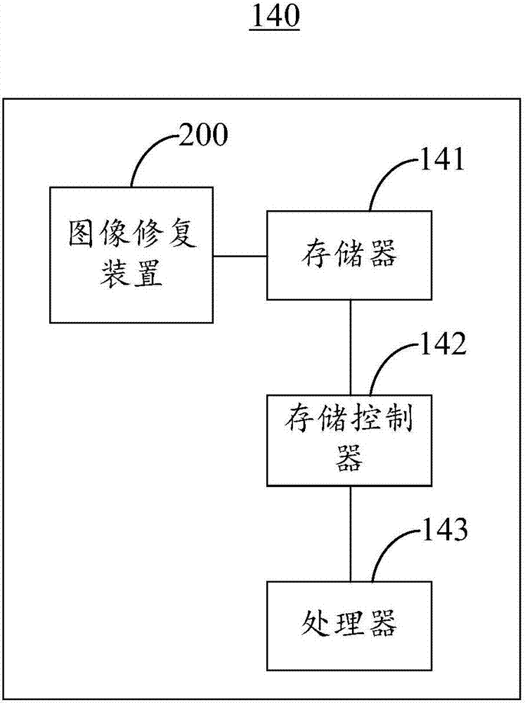
[0096] Please refer to Figure 11 , Figure 11 A schematic block diagram of an image restoration apparatus 200 provided by a preferred embodiment of the present invention is shown. The image restoration device 200 includes an original image restoration module 201 , a light intensity modulation value calculation module 202 , an error area determination module 203 and an image restoration module 204 .

[0097] The original image restoration module 201 is configured to obtain the original image collected by the camera device, wherein the original image is an image of the measured object covered with a sinusoidal grating.

[0098] In the embodiment of the present invention, the original image restoration module 201 may be used to perform step S101.

[0099] The light intensity modulation value calculation module 202 is used to calculate the light intensity modulation value of each pixel in the original image.

[0100] In the embodiment of the present invention, the light intens...


PUM


Abstract

The invention relates to the technical field of image processing and provides an image restoration method and apparatus, and a three-dimensional reconstruction system. The method comprises the steps of obtaining an original image collected by a camera apparatus, wherein the original image is an image of a tested object covered with a sinusoidal grating; calculating a light intensity modulation value of each pixel point in the original image; according to the light intensity modulation value of each pixel point, determining an error region in the original image; and according to a gray value, in a corrected image, of a reference point corresponding to each error pixel point in the error region, performing gray value correction on each error pixel point to obtain a restored image. A model does not need to be built additionally, and the error region is restored by performing the gray value correction on each error pixel point, so that multi-path errors in existing phase measurement profilometry can be effectively reduced and a more accurate three-dimensional reconstruction result can be obtained.

Description

technical field [0001] The present invention relates to the technical field of image processing, in particular to an image restoration method, device and three-dimensional reconstruction system. Background technique [0002] Phase measuring profilometry (PMP) refers to the use of phase time domain encoding to generate multiple projected patterns, which are projected onto the surface of the object to be measured by a projector, and then the surface of the object to be measured is captured by a camera. The reflection information of the measured object is calculated, and then the three-dimensional coordinates of the measured object are calculated, and the three-dimensional reconstruction of the measured object is completed. [0003] In phase measurement profilometry, when there is a region with a sharp change in the reflectivity of the measured target, since the image acquisition of the camera is an integration process, and each integration unit of the camera has a certain size...

Claims


Application Information

Patent Timeline
Patent Type & Authority Applications(China)
IPC IPC(8): G06T5/00G06T7/514G06T7/90
CPCG06T7/514G06T7/90G06T2207/10024G06T5/90
Inventor 刘凯孙伟伦卢勇
Owner SICHUAN UNIV
Learn More