
Substrate mother board and manufacturing method thereof

A manufacturing method and motherboard technology, which are applied in the photoengraving process of pattern surface, semiconductor/solid-state device manufacturing, instruments, etc., can solve the problems of easy generation of debris, waste of manpower and material resources, cost, cracking, etc.

Active Publication Date: 2017-10-17
BOE TECH GRP CO LTD +1
View PDF4 Cites 0 Cited by
  • Summary
  • Abstract
  • Description
  • Claims
  • Application Information

AI Technical Summary

Problems solved by technology

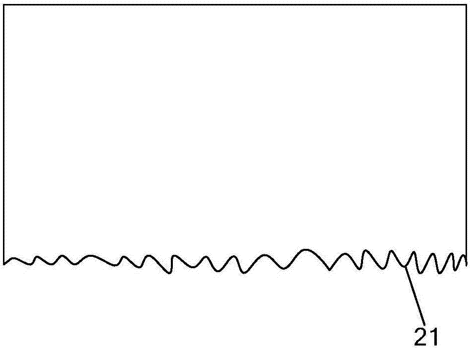
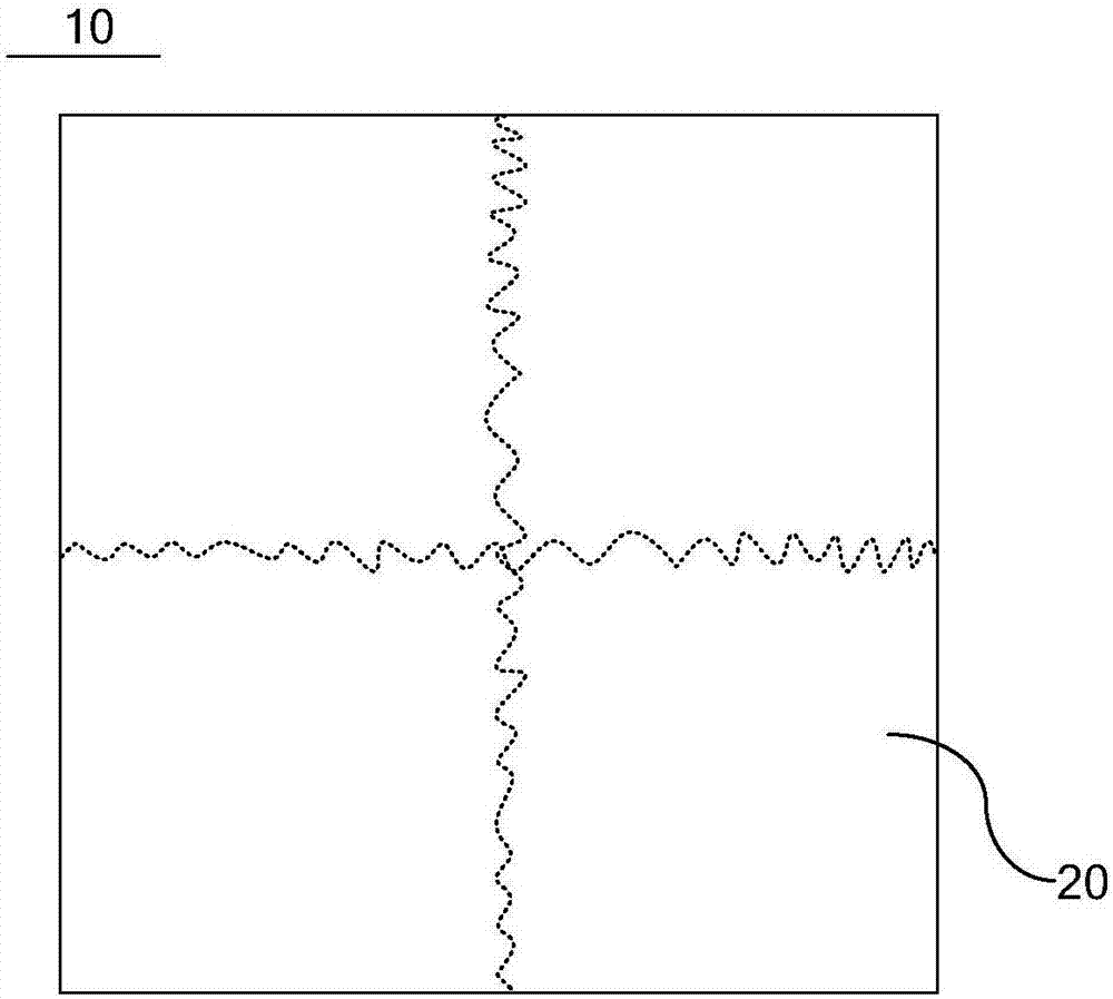
[0003] However, at the cut edge of the motherboard there are such figure 1 As shown in the burr 21, if the cutting edge is edged, it is easy to generate debris splashing around during the edge grinding process, and part of the debris splashes on the motherboard; if the cutting edge is not edged, then Due to the uneven surface of the cutting edge, the burr 21 is in contact with the side wall of the evaporation (EV) chamber or the mask plate during subsequent processes such as metal masking and evaporation on the mother board. On the one hand, it is easy to generate debris. , causing some debris to splash on the motherboard, on the other hand, it is also easy to cause the motherboard to break
Based on the above, when a single array substrate is applied to a display panel, some debris splashes on the display area of ​​the array substrate, or the part of the array substrate located in the display area breaks, which leads to poor display of the display panel, or even scrapping, wasting manpower, material resources and costs

Method used


Image

  • Substrate mother board and manufacturing method thereof
  • Substrate mother board and manufacturing method thereof
  • Substrate mother board and manufacturing method thereof

Examples


Embodiment Construction

[0026] The following will clearly and completely describe the technical solutions in the embodiments of the present invention with reference to the accompanying drawings in the embodiments of the present invention. Obviously, the described embodiments are only some, not all, embodiments of the present invention. Based on the embodiments of the present invention, all other embodiments obtained by persons of ordinary skill in the art without making creative efforts belong to the protection scope of the present invention.

[0027] Those skilled in the art should know that the production process of the display panel may specifically include the following steps:

[0028] In the first step, a part of the structure used for display is made on a larger base substrate to form a larger motherboard (to distinguish it from the smaller motherboard formed in the second step, it can be called the first motherboard plate).

[0029] Here, for motherboards of different types of display panels,...


PUM


Abstract

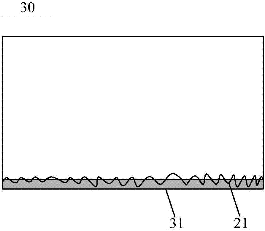
The embodiment of the present invention provides a substrate mother board and a manufacturing method thereof which relate to the display technology field, and can avoid the situation that the fragments formed by the break of the spinous matters splash on the substrate mother board, or the substrate mother board breaks, so that a display panel displays badly. The substrate mother board comprises at least one cutting edge possessing the spinous matters, and also comprises a packaging strip covering the tips of all spinous matters of the cutting edge.

Description

technical field [0001] The invention relates to the field of display technology, in particular to a base plate and a manufacturing method thereof. Background technique [0002] Taking the preparation process of the array substrate motherboard in OLED (Organic Light-Emitting Diode, referred to as light-emitting diode) as an example, in order to improve the production efficiency, firstly, some graphics are formed on the substrate substrate through multiple patterning processes, and then the substrate substrate is processed. cutting to obtain a mother board including a plurality of array substrates. [0003] However, at the cut edge of the motherboard there are such figure 1 As shown in the burr 21, if the cutting edge is edged, it is easy to generate debris splashing around during the edge grinding process, and part of the debris splashes on the motherboard; if the cutting edge is not edged, then Due to the uneven surface of the cutting edge, the burr 21 is in contact with t...

Claims


Application Information

Patent Timeline
IPC IPC(8): H01L27/12H01L51/56G03F7/00G02F1/1333
CPCH01L27/1262G02F1/133351G03F7/00H10K71/00
Inventor 何传友
Owner BOE TECH GRP CO LTD
Learn More