Electric connector

A technology of electrical connectors and connecting materials, which is applied in the direction of connections, circuits, and parts of connection devices, etc. It can solve the problem of increasing the processing difficulty of signal terminals and grounding parts, weakening the anti-interference ability of signal transmission, and affecting the shielding effect of electrical connectors, etc. Problems, to achieve the effect of enhancing anti-interference ability, reducing processing difficulty, and reducing assembly difficulty

Inactive Publication Date: 2017-10-17
DEYI PRECISION ELECTRONIC IND CO LTD PANYU
View PDF11 Cites 8 Cited by
  • Summary
  • Abstract
  • Description
  • Claims
  • Application Information

AI Technical Summary

Problems solved by technology

[0003] However, in order to prevent the signal terminals from short-circuiting against the shield, the signal terminals are not provided with the extension portion abutting against the shield, so that the structure of the signal terminals is different from that of the ground. In actual production, the processing difficulty of the signal terminal and the grounding piece is increased, and during assembly, the operator easily assembles the signal terminal into the storage tube where the grounding piece is located by mistake, so that it does not abut against the shielding piece, Affects the shielding effect of the electrical connector and weakens the anti-interference ability during signal transmission

Method used


Image

  • Electric connector
  • Electric connector
  • Electric connector

Examples


Embodiment Construction

[0029] In order to facilitate a better understanding of the purpose, structure, features, and effects of the present invention, the present invention will now be further described in conjunction with the accompanying drawings and specific embodiments.

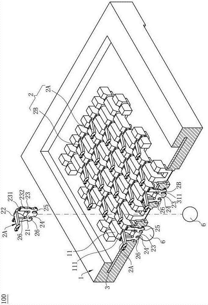
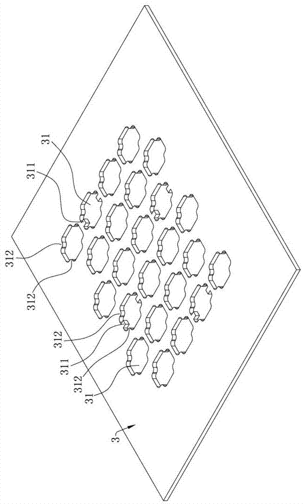
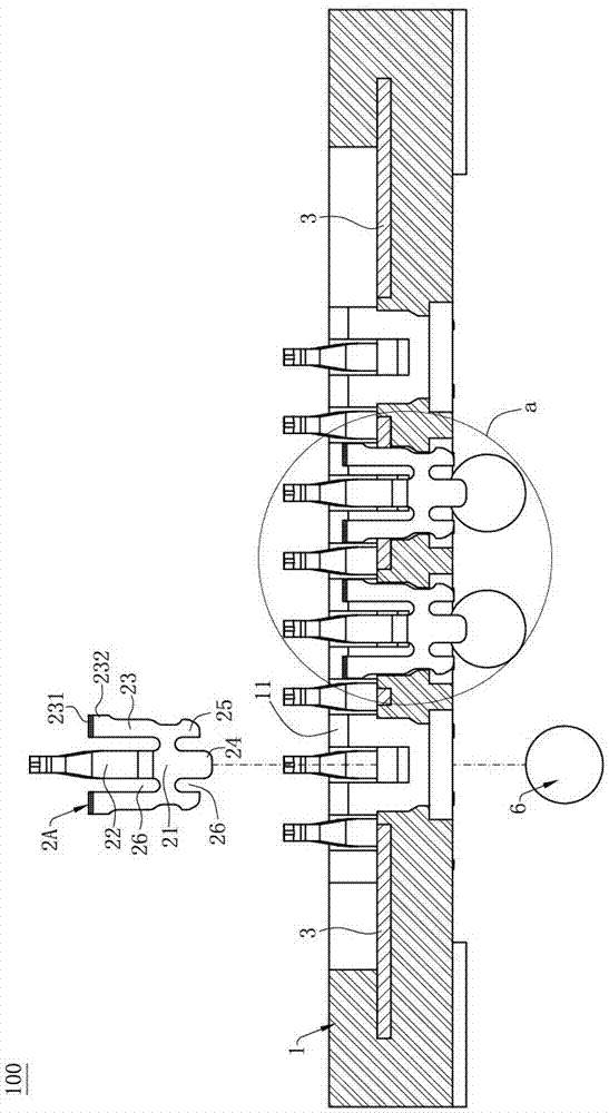
[0030] Such as figure 1 , image 3 and Figure 7 As shown, the electrical connector 100 of the present invention is used to electrically connect a chip module 4 to a circuit board 5, which includes: an insulating body 1; a plurality of terminals 2 respectively correspondingly accommodated in the insulating body 1, including The signal terminal 2A used to contact the signal pad of the chip module 4 to transmit signals, and the ground terminal 2B used to contact the ground pad of the chip module 4, and the structure of the signal terminal 2A and the ground terminal 2B are the same; and A shielding part 3 is disposed on the insulating body 1 , and the shielding part 3 only contacts the ground terminal 2B but does not contact the...


PUM


Abstract

The invention discloses an electric connector. The electric connector comprises an insulation main body, a plurality of grounding terminals and signal terminals which are identical in structures and correspondingly received in the insulation main body and a shielding member; each of the grounding terminals and the signal terminals has a base part, an elastic arm which is formed by bending upwardly and extended from the base part and at least one material connection part which is extended upwardly from the base part; the elastic arm is used for conductively connecting to a chip module; the material connection part is used for connecting to the material belt; the shielding member is arranged on the insulation main body; the shielding member has a plurality of holes, through which the grounding terminals and the signal terminals pass; at least one abutting part is arranged on the shielding member which corresponds to the material connection part of the grounding terminal and is projected from the hole in order to contact the material connection part of the grounding terminal. Because the abutting part is arranged on the shielding member in a protruding manner but not on the grounding terminal, structures of the grounding terminals and the signal terminals are guaranteed to be identical; the processing difficulty and assembling difficulty of the grounding terminals and the signal terminals are reduced, a shielding effect of an electric connector can be guaranteed and an interference resistance capability during signal transmission is enhanced.

Description

technical field [0001] The invention relates to an electrical connector, in particular to an electrical connector capable of preventing electromagnetic interference between signal terminals. Background technique [0002] The Chinese patent with the patent number CN201020663926.6 discloses an electrical connector, including an insulating body, a plurality of signal terminals, a grounding element and a plurality of shielding elements. The insulating body is provided with a plurality of receiving tubes, each The signal terminals are correspondingly accommodated in one of the accommodating tubes, and a plurality of the shielding members are stacked and assembled into the insulating body, each of the shielding members is provided with a plurality of shielding holes, and each of the shielding members is The hole is correspondingly arranged on the periphery of a storage tube, and a slot is provided on the storage tube where the grounding piece is located, and the grounding piece ha...

Claims


Application Information

Patent Timeline
Patent Type & Authority Applications(China)
IPC IPC(8): H01R13/6581H01R13/6597H01R13/02H01R12/71
CPCH01R12/716H01R13/02H01R13/6581H01R13/6597H01R13/2442H01R13/6588H05K7/1069H01R13/41
Inventor 张文昌王永福黄常伟
Owner DEYI PRECISION ELECTRONIC IND CO LTD PANYU
Why Eureka
Try Eureka