High-voltage switch cabinet component assembly working device

A technology for high-voltage switchgear and operating equipment, applied in the direction of switchgear, electrical components, etc., can solve the problems of small working space, low installation efficiency, and high physical exertion, and achieve the effects of convenient positioning, high installation efficiency, and low labor intensity

Inactive Publication Date: 2017-10-17
绵阳行之智汇知识产权服务有限公司
View PDF4 Cites 1 Cited by
  • Summary
  • Abstract
  • Description
  • Claims
  • Application Information

AI Technical Summary

Problems solved by technology

The working space in the cabinet is small, but the current transformer is large in size and heavy in weight, at least thirty to forty kilograms. In the past, when the current transformer was installed in the high-voltage switchgear, it was generally lifted manually, which required three One operator cooperates to complete the installation, which consumes a lot of physical strength and is difficult to install. At the same time, due to the limitation of the operating space, the operator squats down to carry out the operation, which is time-consuming and laborious, and the installation efficiency is low. Three people need to work together to install a set of high-voltage transformers. 45 minutes, and at the same time, there are huge hidden safety hazards in the long-term operation process

Method used


Image

  • High-voltage switch cabinet component assembly working device

Examples


Embodiment 1

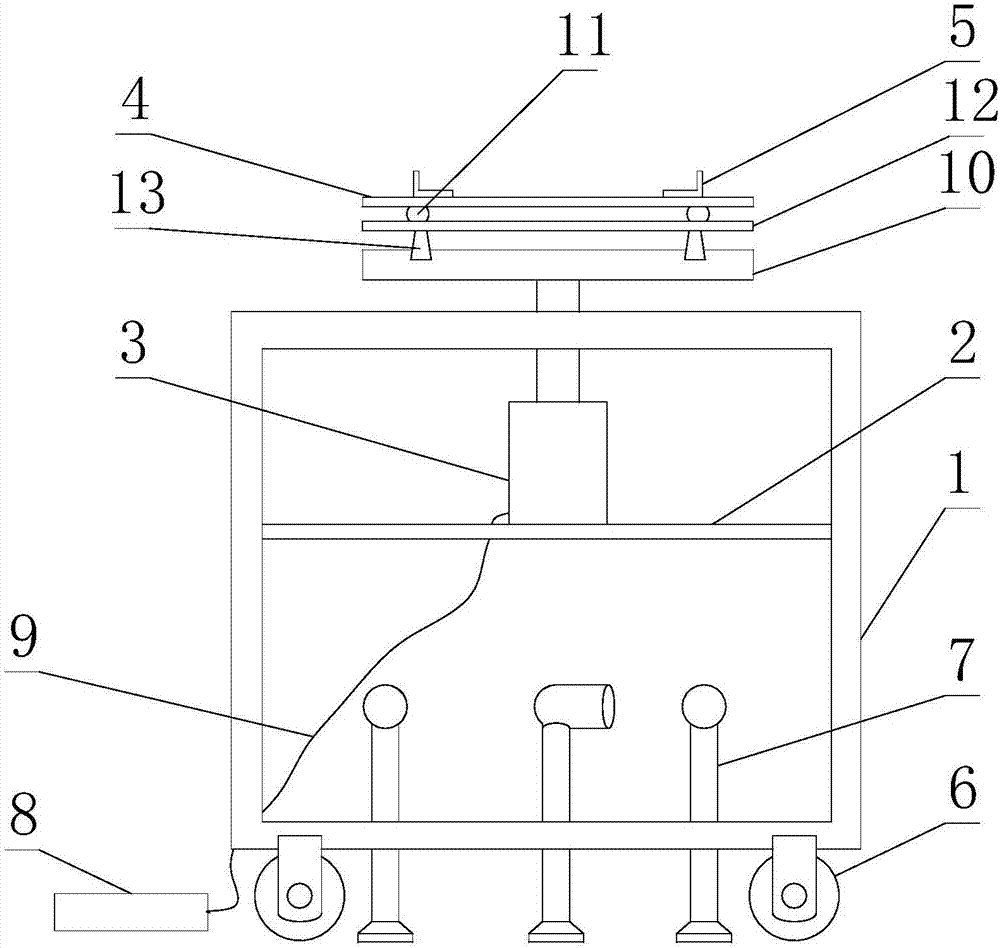
[0032] Such as figure 1As shown, the high-voltage switchgear component assembly operation equipment includes a frame body 1, a jacking device and a pallet 4, and the jacking device is fixed on the frame body 1, and also includes a support plate 10 fixed on the jacking device, The slide rail 13 is arranged between the support plate 10 and the pallet 4, the pallet 4 and the support plate 10 are connected through the slide rail 13, and the slide rail 13 is a linear track.

[0033] Specifically, this operating equipment is used to lift the current transformer to be installed and provide support for the current transformer to be installed. The pallet 4 is used to put the current transformer to be installed, that is, the pallet 4 is on the top Under the action of the lifting device, the corresponding current transformer can be lifted to the installation position. After the position of the current transformer corresponds to the installation position, the corresponding operator can ef...

Embodiment 2

[0037] Such as figure 1 As shown, this embodiment is further limited on the basis of Embodiment 1: As a specific implementation form of the jacking device, the jacking device is a hydraulic cylinder 3, and the frame body 1 is also provided with a mounting seat 2, so The hydraulic cylinder 3 is installed on the mounting seat 2;

[0038] It also includes a foot-operated hydraulic pump 8 and a hose 9, the foot-operated hydraulic pump 8 is connected to the hydraulic cylinder 3 through a hose 9, and the hose 9 is used as a connection between the foot-operated hydraulic pump 8 and the hydraulic cylinder 3 Hydraulic oil lines. In this scheme, the hydraulic cylinder 3 is provided with a pressure medium through the foot-operated hydraulic pump 8. At the same time, since the foot-operated hydraulic pump 8 is connected to the hydraulic cylinder 3 through a hose 9, when the hydraulic cylinder 3 is working, the The foot-operated hydraulic pump 8 is placed on the ground or other platforms...


PUM


Abstract

A high-voltage switch cabinet component assembly working device disclosed by the present invention comprises a rack body, a jacking device and a supporting bench, and the jacking device is fixed to the rack body. The high-voltage switch cabinet component assembly working device also comprises a supporting plate fixed on the jacking device and a sliding rail arranged between the supporting plate and the supporting bench, the supporting bench and the supporting plate are connected via the sliding rail, and the sliding rail is a linear rail. The working device enables a current transformer to be positioned at an installation position conveniently.

Description

technical field [0001] The invention relates to the technical field of current transformer installation auxiliary equipment, in particular to a high-voltage switch cabinet component assembly operation equipment. Background technique [0002] As stated in the invention patent with application number 201610597270.4: high-voltage switchgear is mainly used in power plants, substations and power transformation and distribution places of industrial enterprises to receive and distribute electric energy, control, protect and monitor circuits. The working space in the cabinet is small, but the current transformer is large in size and heavy in weight, at least thirty to forty kilograms. In the past, when the current transformer was installed in the high-voltage switchgear, it was generally lifted manually, which required three One operator cooperates to complete the installation, which consumes a lot of physical strength and is difficult to install. At the same time, due to the limita...

Claims


Application Information

Patent Timeline
Patent Type & Authority Applications(China)
IPC IPC(8): H02B3/00
CPCH02B3/00
Inventor 王伟
Owner 绵阳行之智汇知识产权服务有限公司
Why Eureka
Try Eureka