
Electronic sphygmomanometer

An electronic sphygmomanometer and blood pressure technology, applied in the direction of cardiac catheterization, etc., can solve problems such as inconvenient storage and access, excessive deviation of measurement data, and complicated procedures

Pending Publication Date: 2017-10-20
GUANGDONG UNIV OF TECH
View PDF8 Cites 2 Cited by
  • Summary
  • Abstract
  • Description
  • Claims
  • Application Information

AI Technical Summary

Problems solved by technology

Electronic sphygmomanometers are more suitable for home use, but there are many problems and disadvantages in the use of electronic sphygmomanometers: 1) When wearing the cuff, the body position and arm angle need to be adjusted to keep the center of the cuff consistent with the heart. Cognitive reasons are not conducive to meeting this requirement, resulting in large deviations in measurement data
2) When wearing the cuff, the cuff may fall off from the metal buckle, and it needs to be restored to its original shape before it can be worn. The process is cumbersome and inconvenient for the elderly to operate
3) There are certain requirements for the position where the cuff is worn. After investigation, it was found that some elderly people did not wear the cuff according to the required position due to cognitive reasons, but instead wore it at the elbow joint, resulting in excessive deviation of measurement data.
4) The sphygmomanometer includes a cuff, a trachea, and a main body. The operation process is more complicated when used, and it is not easy to store and take out

Method used


Image

  • Electronic sphygmomanometer
  • Electronic sphygmomanometer
  • Electronic sphygmomanometer

Examples


Embodiment Construction

[0024] The following will clearly and completely describe the technical solutions in the embodiments of the present invention with reference to the accompanying drawings in the embodiments of the present invention. Obviously, the described embodiments are only some, not all, embodiments of the present invention. Based on the embodiments of the present invention, all other embodiments obtained by persons of ordinary skill in the art without making creative efforts belong to the protection scope of the present invention.

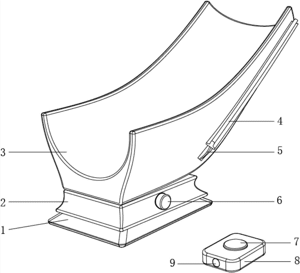
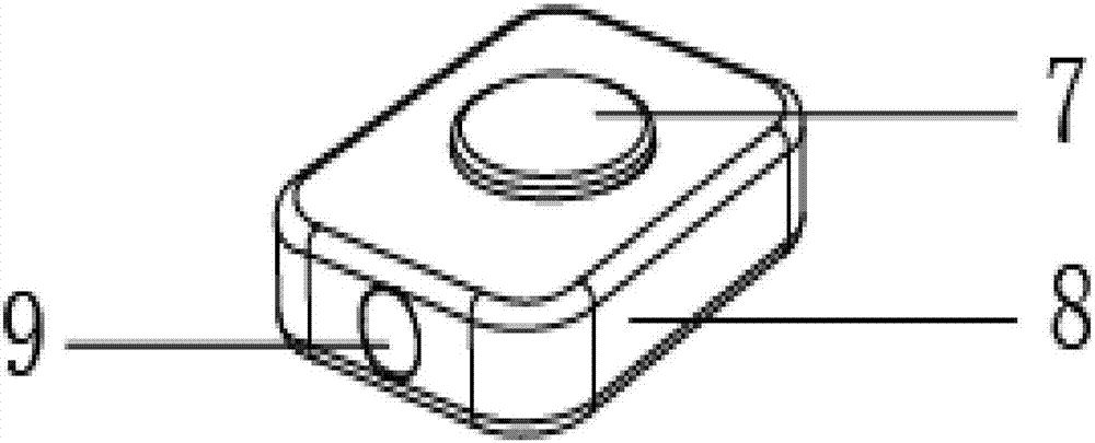
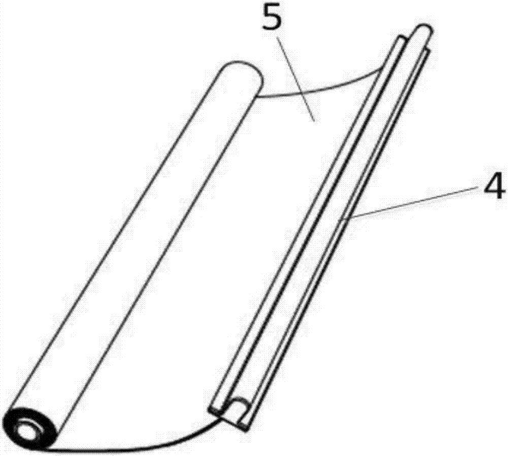
[0025] Please refer to figure 1 , figure 1 It is a schematic diagram of the overall structure of a specific embodiment provided by the present invention; figure 2 for figure 1 The schematic diagram of the prompt system structure is shown.

[0026] In a specific embodiment provided by the present invention, the electronic sphygmomanometer mainly includes a support platform 3, an electronic measuring element 2, a cuff 5 and a prompt system.

[0027] Wherein...


PUM


Abstract

The invention discloses an electronic sphygmomanometer. The electronic sphygmomanometer comprises a support table, an electronic measuring element, a sleeve band and a prompt system, wherein the support table is provided with a groove structure, the electronic measuring element is arranged on the support table and used for measuring blood pressure, the sleeve band is arranged on the side edge of the support table in an extensible mode, a pressure sensor and an air inflation and deflation component are arranged in the sleeve band and connected with the electronic measuring element, and the prompt system is connected with the electronic measuring element and used for prompting measured blood pressure results. According to the electronic sphygmomanometer, the groove structure is added, so that old people find right measuring gestures and measuring parts more conveniently and accurately, and through a tensile sleeve band structure, the problem that old people have difficulty in operating by a single hand is solved. Meanwhile, only by starting the electronic measuring element, can blood pressure measuring be completed, the using operating steps of the sphygmomanometer are simplified, and the sphygmomanometer helps old people to conduct real-time blood pressure measuring conveniently and accurately.

Description

technical field [0001] The invention relates to the technical field of medical instruments, in particular to an electronic sphygmomanometer. Background technique [0002] With the continuous progress of society and the continuous improvement of material living standards, people pay more and more attention to the health problems of the elderly at home, such as monitoring the blood pressure of the elderly in daily life. [0003] At present, auscultation sphygmomanometers and oscillometric sphygmomanometers are commonly used in China with high accuracy, such as mercury sphygmomanometers and electronic sphygmomanometers. Electronic sphygmomanometers are more suitable for home use, but there are many problems and disadvantages in the use of electronic sphygmomanometers: 1) When wearing the cuff, the body position and arm angle need to be adjusted to keep the center of the cuff consistent with the heart. Cognitive reasons are not conducive to meeting this requirement, resulting i...

Claims


Application Information

Patent Timeline
IPC IPC(8): A61B5/0225
CPCA61B5/02141A61B5/02233A61B5/0225
Inventor 胡飞潘莉黄启哲陈干郭统任彭凌
Owner GUANGDONG UNIV OF TECH
Learn More