A processing method of high flatness metal ultra-thin plate

A processing method and ultra-thin plate technology, applied in the field of abrasive grain processing, can solve the problems that cannot be adopted, can not realize high-flatness metal ultra-thin plate processing, clamping deformation and deformation are difficult to control, etc., so as to achieve easy control of deformation and avoid surface Unstable shape and effective control of clamping deformation

Active Publication Date: 2019-01-15
DALIAN UNIV OF TECH
View PDF9 Cites 0 Cited by
  • Summary
  • Abstract
  • Description
  • Claims
  • Application Information

AI Technical Summary

Problems solved by technology

Secondly, the metal material is non-transparent, and it is impossible to use the optical glue technology that can effectively reduce the bonding deformation.
Therefore, the existing ultra-thin plate processing method that combines the thickening of the original part thickness and the optical glue plate technology cannot realize the processing of high-flatness metal ultra-thin plates
[0004] Chinese Patent No. CN201710089820.6 discloses "A Method for Making a Viscoelastic Pad and a Surface Grinding Method for Thin-plate Workpieces" by Zhou Ping et al. The viscoelastic pad is used to reduce the adsorption and clamping deformation of the thin-plate workpiece by the electromagnetic sucker. Grinding machines process metal thin plate workpieces to obtain thin steel plates with a surface accuracy of PV 5.5m (thin steel plates are 110mm long, 100mm wide, and 5mm thick). However, when this technology is used for ultra-thin plates with a larger diameter-thickness ratio, the clamp deformation and deformation caused by grinding residual stress becomes very difficult to control, moreover, this method is only suitable for ferromagnetic material sheet processing

Method used


Image

  • A processing method of high flatness metal ultra-thin plate
  • A processing method of high flatness metal ultra-thin plate
  • A processing method of high flatness metal ultra-thin plate

Examples


Embodiment Construction

[0035] The present invention will be described in detail below in conjunction with the accompanying drawings and specific embodiments.

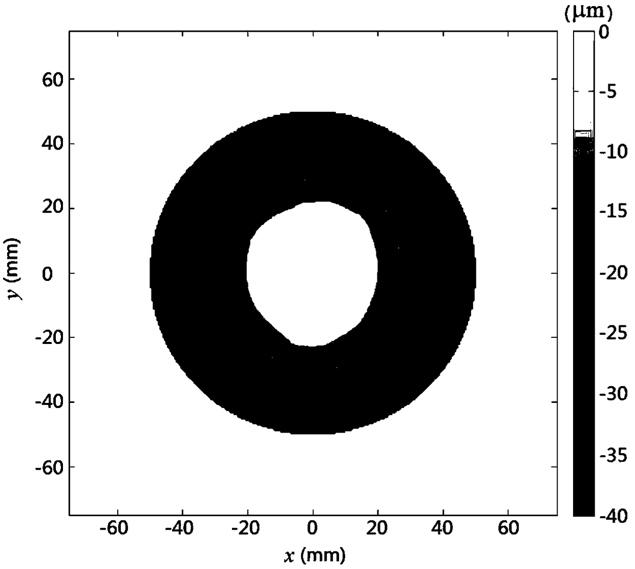
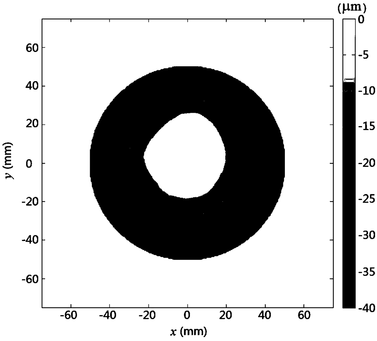
[0036] An ultra-thin copper plate for testing, the material is T2 pure copper, the required diameter is 150mm, the thickness is 3mm, the diameter-to-thickness ratio is 50, and the surface shape accuracy reaches PV<10μm within the effective diameter range of 120mm.

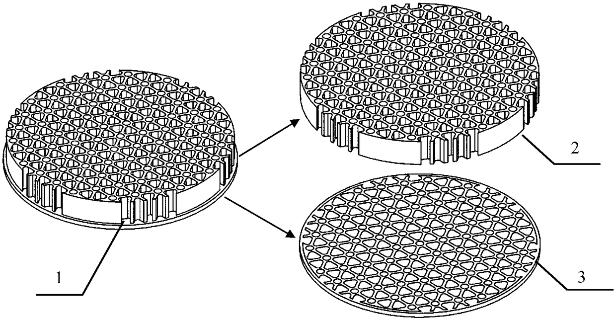
[0037] The initial size of the copper block is 150mm in diameter and 20mm in thickness. On one side, blind holes with a depth of 16.5mm and an equivalent diameter of 6-10mm are processed by milling technology. The wall thickness between the holes is 2mm. Carry out stress-relief annealing on hollow blank 1 to eliminate residual stress, annealing temperature is 280° C., heat preservation for 4 hours, and furnace cooling. The hollow support structure 3 can effectively reduce the internal residual stress after annealing, thereby effectively suppressing the additional deformation cause...


PUM


Abstract

The invention discloses a high-flatness metal super-thin plate machining method. According to the method, the side along the thickness direction of an initial blank is machined for removing a portion of material which is machined into a hollowed-out blank; the hollowed-out side of the hollowed-out blank serves as a hollowed-out supporting structure for subsequent machining; the other side of the hollowed-out blank serves as a subsequent super-thin plate part blank; through the hollowed-out supporting structure, the residual stress inside a part can be effectively released; through the combination with a stress-relief annealing process, the buckling deformation caused by the release of the residual stress inside the part can be effectively controlled when a super-thin plate is cut out of a thick metal plate; a pore structure or a groove structure is machined on the supporting structure, so that the glue layer thickness and the bonding deformation are effectively reduced by glue permeation through capillarity, and the clamping deformation can be effectively controlled; meanwhile, the super-thin plate is loaded onto a disc through a substrate of the same material, the thermal deformation caused by a temperature gradient in the machining process can be reduced; and the paraffin or rosin cerate bonding mode is adopted for the method instead of an electromagnetic chuck, and thus the method can be applied to the machining of a non-ferromagnetic material.

Description

technical field [0001] The invention relates to a processing method of a high flatness metal ultra-thin plate, which belongs to the field of abrasive grain processing. Background technique [0002] At present, the application range of metal ultra-thin plate parts is very wide, and its dimensional accuracy and shape and position accuracy often have a great impact on the performance of parts. Common parts of this type are gaskets, friction plates, templates and ultra-thin mirrors. The thickness of thin plate parts is one or even two orders of magnitude smaller than the length (or diameter), and the most typical mechanical characteristics are extremely low stiffness, and the deformation caused by various forces and temperatures during processing is very obvious. In order to increase the rigidity during thin plate processing, the workpiece to be processed and the support structure must be fixed by the upper plate process, and the workpiece and the support structure shall be sep...

Claims


Application Information

Patent Timeline
Patent Type & Authority Patents(China)
IPC IPC(8): B23P15/00
CPCB23P15/00
Inventor 周平闫英赵炳尧金洙吉康仁科郭东明
Owner DALIAN UNIV OF TECH
Why Eureka
Try Eureka