

Steel tube filling cutting equipment
A technology for cutting equipment and steel pipes, which is applied in the field of steel pipe filling and cutting equipment, which can solve the problems of injury to handling personnel, uneven cutting end faces, and low efficiency, and achieve the effects of improving cutting efficiency, reducing labor intensity, and simple operation
Active Publication Date: 2017-10-20
湖北国通领驭建设集团有限公司
View PDF4 Cites 8 Cited by
- Summary
- Abstract
- Description
- Claims
- Application Information
AI Technical Summary
Problems solved by technology
[0003] Traditionally, the cutting of steel pipes is to manually place the steel pipe on the cutting tool, and cut one end of the steel pipe to a fixed length by pushing the steel pipe back and forth. Since the inside of the steel pipe is a hollow structure, if the steel pipe is relatively strong, it will be cut. The wall thickness of the steel pipe is relatively thin, and it is easy to make the cut end surface concave when cutting, resulting in uneven cutting end surface, and the traditional cutting can only cut one piece at a time, which is less efficient. If the cutting process is relatively Slow, there will be burrs on the cut end face, and when the cut steel pipe is transported, it may hurt the transporter. Therefore, in order to solve these situations, it is very important to design a filling cutting equipment. Necessary
Method used
View moreImage
Smart ImageViewing Examples

Examples
Embodiment 2
[0024] Embodiment 2: The hydraulic stretching rod 17 can be replaced by an electronically controlled telescopic rod, which can also achieve the stretching effect, and other structures are the same as in Embodiment 1.
Login to View More PUM
 Abstract
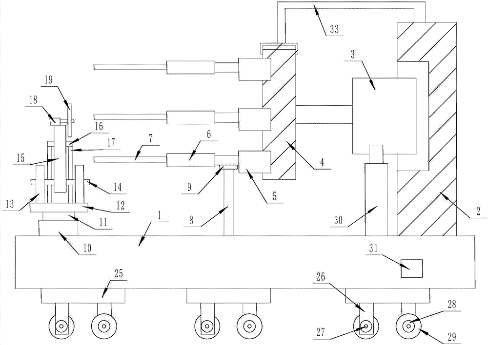
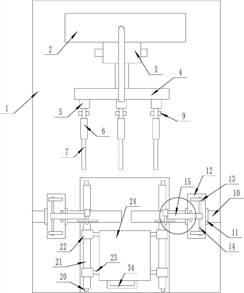
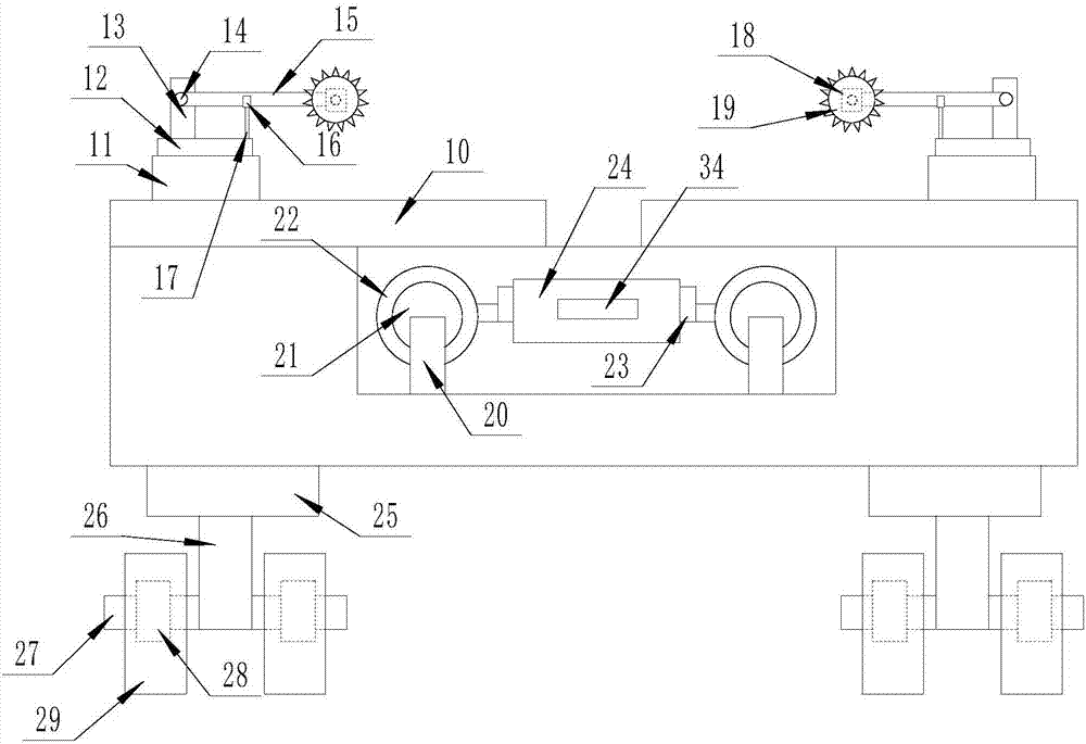
The invention discloses steel tube filling cutting equipment. The steel tube filling cutting equipment comprises a strip-shaped bearing pedestal, wherein a steel tube inner filling structure is arranged at one end of the upper surface of the strip-shaped bearing pedestal; a cutting mechanism is arranged at the other end of the upper surface of the strip-shaped bearing pedestal; a waste residue collecting mechanism is arranged on the center of the upper surface of the strip-shaped bearing pedestal; and a moving mechanism is arranged on the lower surface of the strip-shaped bearing pedestal. The steel tube filling cutting equipment has the beneficial effects that operation is relatively simple, manual holding is only required, labor intensity is relieved, cutting efficiency is improved, and the cut end surface is guaranteed to be not deformed during cutting; and meanwhile, the cut end surface also can be effectively grinded, so that cutting of steel tubes of different diameter sizes can be adapted.
Description
technical field [0001] The invention relates to the field of steel pipe cutting, in particular to a steel pipe filling and cutting equipment. Background technique [0002] Steel pipes are usually used in different places and require different lengths, so they need to be cut to a certain length. [0003] Traditionally, the cutting of steel pipes is to manually place the steel pipe on the cutting tool, and cut one end of the steel pipe to a fixed length by pushing the steel pipe back and forth. Since the inside of the steel pipe is a hollow structure, if the steel pipe is relatively strong, it will be cut. The wall thickness of the steel pipe is relatively thin, and it is easy to make the cut end surface concave when cutting, resulting in uneven cutting end surface, and the traditional cutting can only cut one piece at a time, which is less efficient. If the cutting process is relatively Slow, there will be burrs on the cut end face, and when the cut steel pipe is transported...
Claims
Login to View More Application Information
Patent Timeline
 Patent Type & AuthorityApplications(China)
IPC IPC(8): B23P23/04
CPCB23P23/04
Inventor徐文斌
Owner湖北国通领驭建设集团有限公司