Fireproof exhaust valve

A technology for exhaust valves and air inlets, which is applied in the direction of safety valves, balance valves, valve devices, etc., and can solve the problem that the ceiling elevation of the room cannot be reached, the height of the fire-proof exhaust valve cannot be raised, and the maximum opening angle cannot be realized, etc. question

Pending Publication Date: 2017-10-20
深圳市万居科技股份有限公司
View PDF6 Cites 0 Cited by
  • Summary
  • Abstract
  • Description
  • Claims
  • Application Information

AI Technical Summary

Problems solved by technology

[0003] The purpose of the present invention is to provide a fire-proof exhaust valve, which aims to solve the problems in the prior art that the height of the fire-proof exhaust valve cannot be raised and the ceiling height of the room cannot be raised and the maximum opening angle cannot be achieved when the pipe wall thickness changes. gas problem

Method used


Image

  • Fireproof exhaust valve
  • Fireproof exhaust valve
  • Fireproof exhaust valve

Examples


Embodiment 1

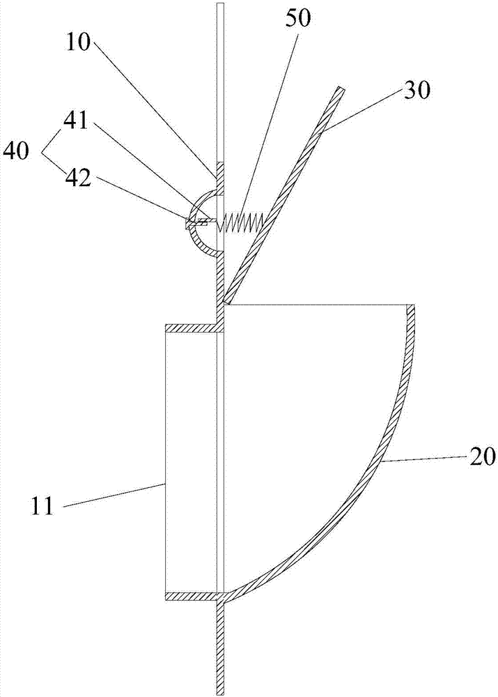
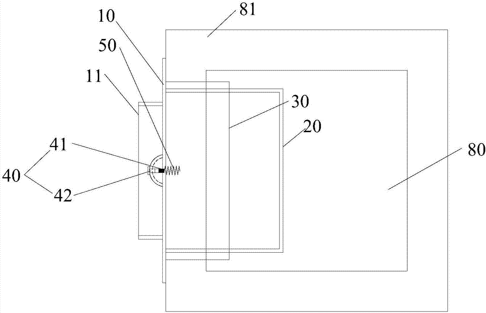
[0026] Reference Figure 2 to Figure 4 , The fire prevention exhaust valve provided by the first embodiment of the present invention includes a panel 10 provided with an air inlet 11, a guide pipe 20 arranged on one side of the panel 10 and communicating with the air inlet 11, and a fireproof exhaust valve arranged above the outlet of the guide pipe 20 The cover plate 30 and the fuse 40 arranged between the panel 10 and the fire cover plate 30. The fire exhaust valve also includes an elastic member 50 with spring performance for adjusting the angle between the fire cover plate 30 and the horizontal plane. One end of the piece 50 is connected to the movable end 41 of the fuse 40, the fixed end 42 of the fuse 40 is fixed on the panel 10, and the other end of the elastic piece 50 is connected to the fireproof cover 30.

[0027] In this embodiment, the elastic member 50 is a spring or an elastic piece.

[0028] by image 3 , Figure 4 It can be seen that a spring is provided between t...

Embodiment 2

[0030] Reference Figure 5 , Image 6 The difference between this embodiment and the first embodiment is that a normally closed non-return sheet 60 is also provided at the exit of the guide tube 20 and under the fire cover 30. When the exhaust fan is exhausting into the pipeline, the non-return flap 60 is opened and the gas is discharged into the pipeline through the outlet. When the exhaust fan stops exhausting into the pipeline, the non-return flap 60 will fall back to a normally closed state to prevent backflow of gas in the exhaust duct . The similarities between this embodiment and the first embodiment will not be repeated here.

Embodiment 3

[0032] Reference Figure 7 , Figure 8 In this embodiment, an enclosure 70 is added on the basis of the second embodiment. Specifically, the enclosing plate 70 is arranged on the outer side of the guide pipe 20, and its purpose is to use the principle of Berger’s equation to reduce the positive pressure of the air inlet 11 or even reach the negative pressure, which is beneficial to the gas discharge into the exhaust duct. The similarities between this embodiment and the third embodiment will not be repeated here.


PUM


Abstract

The invention relates to the technical field of residence sharing exhaust passage systems, and provides a fireproof exhaust valve. The fireproof exhaust valve comprises a panel provided with an intake port, a guide pipe arranged on one side of the panel and communicating with the intake port, a fireproof cover plate arranged above an outlet of the guide pipe, and a fuser arranged between the panel and the fireproof cover plate. The fireproof exhaust valve further comprises an elastic piece with the spring performances and used for adjusting an included angle between the fireproof cover plate and the horizontal plane; one end of the elastic piece is connected with a movable end of the fuser; and the other end of the elastic piece is connected with the fireproof cover plate. In the fireproof exhaust valve, as the included angle between the fireproof cover plate and the horizontal plane is adjusted, when the fireproof exhaust valve is mounted, the included angle between the fireproof cover plate and the horizontal plane is reduced; and after the fireproof exhaust valve is mounted, the included angle between the fireproof cover plate and the horizontal plane is maximized, the height of the penal of the valve is lowered, the room ceiling elevation is increased, the room space height is increased, and the included angle between the fireproof cover plate and the horizontal plane is maximal to achieve the highest exhaust effect.

Description

Technical field [0001] The invention relates to the technical field of residential shared exhaust ducts, and more specifically, to a fire-proof exhaust valve installed at the air inlet of a shared exhaust duct system. Background technique [0002] Such as figure 1 As shown, currently, in the fire exhaust valve 10' installed in the shared exhaust duct 30' system, the panel 11' is connected to the fire cover 13' through the fuse 12', and the fire cover 13' forms a fixed angle with the horizontal plane. In this way, the fire exhaust valve 10' has the following defects: 1. The height of the panel 11' must be higher than the fire cover 13' in order to seal the valve installation opening 20'. Therefore, it cannot be achieved by reducing the height of the fire exhaust valve 10'. The purpose of the ceiling elevation of the room; 2. When the thickness of the pipe wall changes, the maximum opening angle cannot be reached to achieve the maximum exhaust effect. Summary of the invention [00...

Claims


Application Information

Patent Timeline
Patent Type & Authority Applications(China)
IPC IPC(8): F16K17/38
CPCF16K17/383
Inventor 张琦
Owner 深圳市万居科技股份有限公司
Why Eureka
Try Eureka