
Chimney having automatic direction adjustment function

A technology of automatic adjustment and chimney, which is applied in the direction of combustion method, combustion product treatment, exhaust gas device, etc., to achieve the effect of complete combustion, accelerated flue gas emission, and simple structure

Active Publication Date: 2017-10-20
马枭天
View PDF9 Cites 1 Cited by
  • Summary
  • Abstract
  • Description
  • Claims
  • Application Information

AI Technical Summary

Problems solved by technology

[0003] A few days ago, I heard a report from a classmate who lived in a high-rise residence that in windy weather, smoke would come out from the exhaust port of the range hood of the people who do not cook. After investigation out of curiosity, I found that the original exhaust The smoke outlets are all connected in parallel to a main exhaust outlet and come out from the roof. The range hood of the cooking family has an induced draft fan, and the smoke is exhausted to the main exhaust outlet, but the outlet is blocked by the strong wind and is exhausted by the induced draft fan. The smoke has to flow to the house where there is no wind pressure

Method used


Image

  • Chimney having automatic direction adjustment function
  • Chimney having automatic direction adjustment function
  • Chimney having automatic direction adjustment function

Examples


Embodiment 1

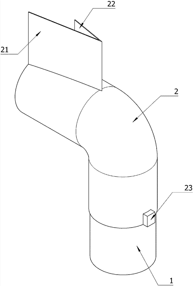
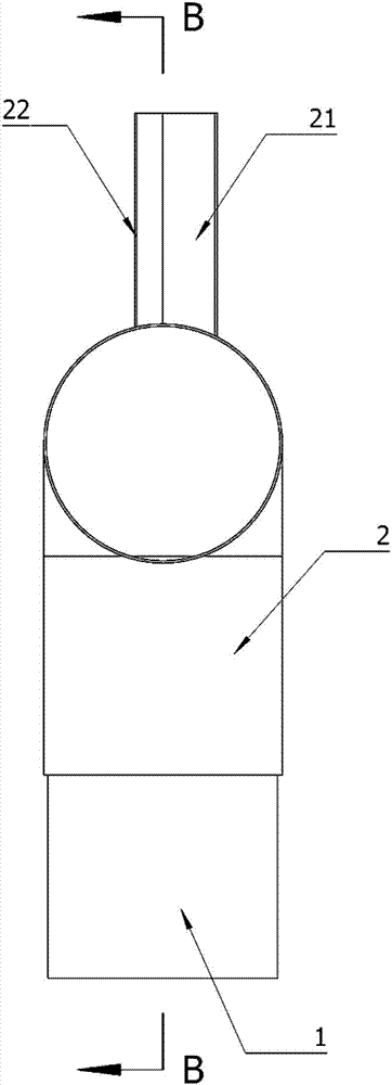
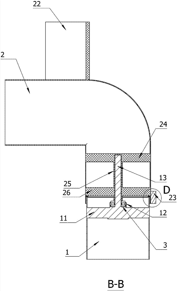
[0031] The structure of the chimney that automatically adjusts its direction is as Figure 1 to Figure 8 As shown, including: lower chimney 1, upper chimney 2;

[0032] see image 3 , Figure 5 , the inner wall of the lower chimney 1 is provided with several lower support rods 11, the upper part of the lower support rods 11 is provided with a bearing disc 12, which accommodates the plane thrust bearing 3, and a vertical shaft 13 placed vertically is arranged in the middle of the bearing disc 12. A smoke baffle 14 is set under the plate 12; the lower support rod 11 can fix the bearing plate 12, the vertical shaft 13, and the smoke baffle 14 on the inner wall of the lower chimney 1, and the smoke baffle 14 can prevent the hot smoke from directly impacting the bearing Disc, cooling can prolong the service life of the bearing.

[0033] see image 3 , Figure 6 , the upper chimney 2 is a bent pipe with a pipe diameter slightly larger than that of the lower chimney 1, so that a...

Embodiment 2

[0040] see Figure 8 , the basic scheme is the same as in Embodiment 1, the difference is that the large guide piece 21 of the upper chimney 2 is changed into a bent large piece 211, that is, the large guide piece 21 is bent from the middle, and the bending angle is 160 degrees. The purpose of bending is to make the windward areas of the large guide piece 21 and the small guide piece 22 equal, and the equal wind resistance on both sides can make the direction of the smoke outlet of the upper chimney 2 completely consistent with the wind direction, and obtain the greatest "wind pulling" effect. And before upper chimney 2 static balance, when chaotic wind blows to the middle of guiding small piece 22 and bending large piece 211, the wind resistance that bending big piece 211 suffers is bigger than flat plate, can accelerate the speed of turning.


PUM


Abstract

A chimney having the automatic direction adjustment function comprises a lower smoke pipe and an upper smoke pipe. A vertical shaft arranged on the axis of the lower smoke pipe is fixed to lower supporting rods. The upper smoke pipe is a bent pipe. The pipe diameter of the upper smoke pipe is slightly larger than that of the lower smoke pipe. The top of the upper smoke pipe is perpendicularly provided with two guide flat plates. The area of the large guide plate is once that of the small guide plate. The area of the large guide plate should guarantee that under the condition of breeze wind lower than force 3, the large guide plate can still push the upper smoke pipe to smoothly rotate. The included angle between the large guide plate and the small guide plate is 5-40 degrees. The inner wall of the straight pipe portion of the upper smoke pipe is provided with upper supporting rods and middle supporting rods. A round pipe is arranged at the center line of the pipe wall of the upper smoke pipe, and the round pipe is fixed between the upper supporting rods and the middle supporting rods. During assembly, the vertical shaft of the lower smoke pipe is sleeved with the round pipe. In this way, the upper smoke pipe can freely rotate on the lower smoke pipe. The chimney having the automatic direction adjustment function has the effects that the backward flow phenomenon is completely eradiated, the draft effect is achieved, smoke discharge is accelerated, and combustion is safer.

Description

technical field [0001] The invention belongs to the field of environmental protection facilities, and in particular relates to a chimney for automatically adjusting direction, which is suitable for an outlet where flammable, explosive, poisonous and harmful gases are discharged up to standard after burning. Background technique [0002] During the study holiday, I went to the home of my classmates in the mountainous area to experience life. I found that the firewood stove in their home, in windy weather, the smoke often flows backwards, even if the wind direction is not directly towards the smoke outlet. After careful observation, it was found that the strong wind blows When passing through the smoke outlet, an air curtain is formed, which prevents the smoke from getting out, and has to be poured into the kitchen, making a smoky atmosphere. When I went back to the urban area to observe the small chimneys in the factory, most of them wore a conical "hat" on the top of the chi...

Claims


Application Information

Patent Timeline
Patent Type & Authority Applications(China)
IPC IPC(8): F23J11/02
CPCF23J11/02
Inventor 马枭天
Owner 马枭天
Learn More