
Transmission line insulator leakage current online monitoring method and system

A leakage current and transmission line technology, which is applied in the field of on-line monitoring method and system for leakage current of insulators of transmission lines, can solve the problems of high data communication cost and low accuracy of leakage current monitoring results.

Inactive Publication Date: 2017-10-20
江苏尚坤电能科技有限公司
View PDF5 Cites 10 Cited by
  • Summary
  • Abstract
  • Description
  • Claims
  • Application Information

AI Technical Summary

Problems solved by technology

[0004] The purpose of the present invention is to provide an on-line monitoring method and system for the insulator leakage current of transmission lines, which is used to solve the technical problems of high data communication cost and low accuracy of leakage current monitoring results in the existing insulator leakage current monitoring system

Method used


Image

  • Transmission line insulator leakage current online monitoring method and system
  • Transmission line insulator leakage current online monitoring method and system
  • Transmission line insulator leakage current online monitoring method and system

Examples


Embodiment 1

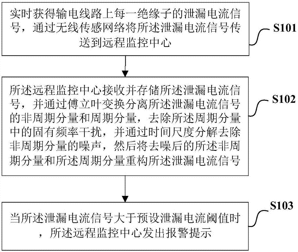
[0056] Such as figure 1 As shown, the invention provides a method for on-line monitoring of leakage current of transmission line insulators. Specifically, the method includes the following steps:

[0057] S101. Obtain the leakage current signal of each insulator on the transmission line in real time, and transmit the leakage current signal to the remote monitoring center through the wireless communication network;

[0058] S102. The remote monitoring center receives and stores the leakage current signal, and separates the non-periodic component and the periodic component of the leakage current signal through Fourier transform, removes the natural frequency interference in the periodic component, and decomposes it by time scale removing the noise of the non-periodic component, and then reconstructing the leakage current signal from the denoised non-periodic component and the periodic component;

[0059] S103. When the leakage current signal is greater than a preset leakage cu...

Embodiment 2

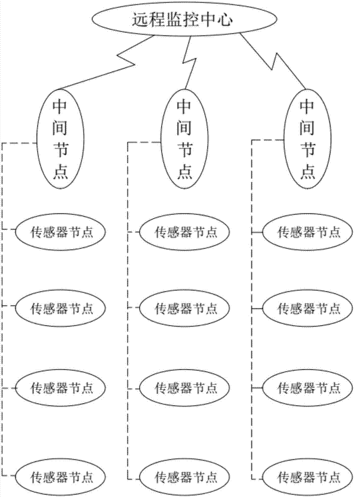
[0093] Based on the same inventive concept, another aspect of the present invention, such as figure 2 As shown, a transmission line insulator leakage current online monitoring system is provided, including a sensor node, an intermediate node and a remote monitoring center, the sensor node is set on each insulator of each transmission line, and the real-time Leakage current signal: The sensor node on the transmission line of each phase communicates with the intermediate node through the ZigBee wireless communication protocol, and the leakage current signal on the transmission line of each phase is transmitted to the substation monitoring terminal through the intermediate node, The substation monitoring terminal is transmitted to the remote monitoring center through an optical fiber network;

[0094] The remote monitoring center is used to receive and store the leakage current signal, and separate the non-periodic component and the periodic component of the leakage current sign...


PUM


Abstract

The invention discloses a transmission line insulator leakage current online monitoring method and a system in order to solve the technical problem that the existing insulator leakage current monitoring system has the disadvantages of high data communication cost and low accuracy of leakage current monitoring results. The method includes the following steps: a leakage current signal of each insulator on a transmission line is obtained in real time, and transmitted to a remote monitoring center through a wireless communication network; the remote monitoring center receives and stores each leakage current signal, separates a non-periodic component and a periodic component of the leakage current signal through Fourier transformation, removes inherent frequency interference in the periodic component, removes the noise in the non-periodic component through time scale decomposition, and uses the de-noised non-periodic component and the periodic component to reconstruct the leakage current signal; and if there is a leakage current signal greater than a preset leakage current threshold, the remote monitoring center issues a warning.

Description

technical field [0001] The invention relates to the technical field of power equipment, in particular to an on-line monitoring method and system for insulator leakage current of transmission lines. Background technique [0002] Insulators in high-voltage transmission lines are responsible for the dual functions of electrical insulation and mechanical support. To ensure the normal operation of transmission lines under overvoltage conditions, the working status of insulators will play an extremely important role in the safe and reliable operation of power systems. Relevant data show that the degree of harm and the economic loss caused by pollution flashover accidents of high-voltage transmission line insulators have far exceeded the impact of operating overvoltage and lightning impulse overvoltage on the power system. In order to prevent pollution flashover accidents, it is necessary to make timely and accurate judgments on the pollution status of insulators, so that necessary...

Claims


Application Information

Patent Timeline
IPC IPC(8): G01R31/02G01R19/25G01D21/02
CPCG01D21/02G01R19/2506G01R31/50
Inventor 俞春华杜永刚
Owner 江苏尚坤电能科技有限公司
Learn More