Flying probe test machine fast alignment method

A flying probe testing machine, fast technology, applied in printed circuit testing, electronic circuit testing, etc., can solve the problems of low production efficiency, long time consumption, and long time consumption, and achieve the effect of improving work efficiency

Active Publication Date: 2017-10-20
SHENZHEN MICRONIC TECH
View PDF10 Cites 5 Cited by
  • Summary
  • Abstract
  • Description
  • Claims
  • Application Information

AI Technical Summary

Problems solved by technology

[0003] During the testing process of the flying probe tester, the test data is first retrieved, the PCB board is placed, and then the alignment points are aligned with the CCD camera. In most cases, the test data has preset alignment points, and only Check on the PCB board, start to test the board after the check is com

Method used


Image

  • Flying probe test machine fast alignment method
  • Flying probe test machine fast alignment method

Examples


Embodiment Construction

[0020] The present invention will be described in detail below with reference to the drawings and specific embodiments.

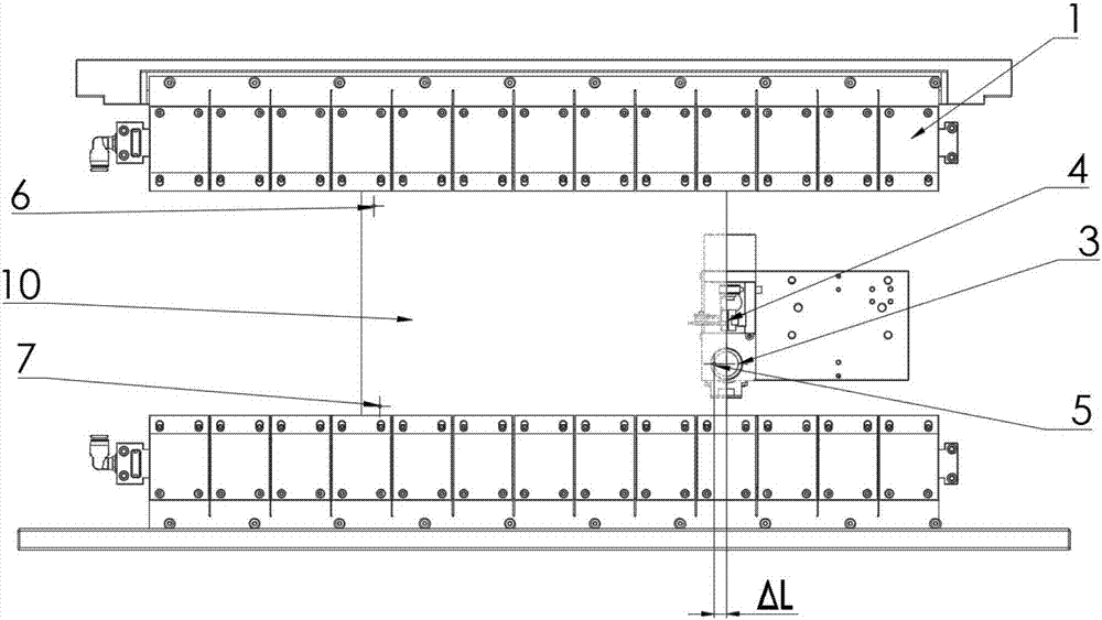
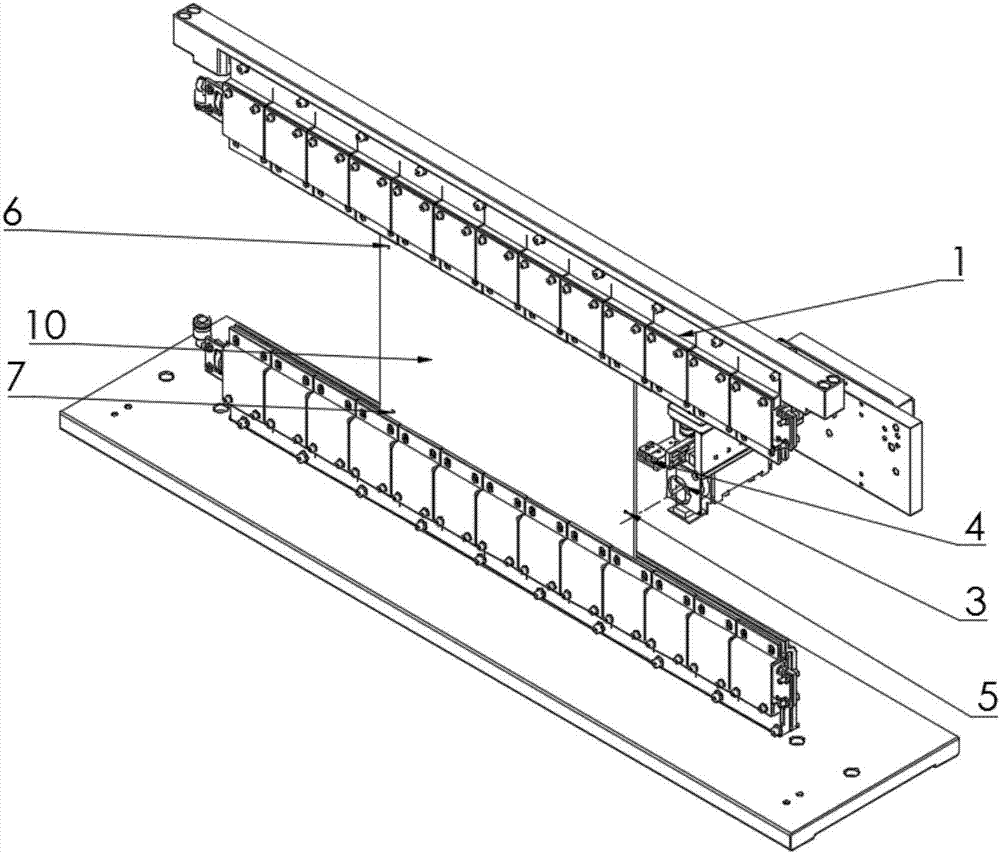
[0021] See figure 1 , The present invention provides a fast alignment method for a flying probe tester, the flying probe tester includes one or more test shafts, wherein at least one test shaft is provided with a test probe and a CCD camera, and the alignment The method includes the following steps:

[0022] The first step: Take any PCB board 10 to be tested with a regular shape and install it in the fixture 1 of the flying probe tester;

[0023] Step 2: Retrieve the test data corresponding to the PCB board 10, the test data includes the distance ΔL from the edge of the PCB board 10 to the first alignment point 5 in the X-axis direction, and the test data also includes The angle and distance between the alignment points, the angle and distance between the CCD camera 3 and the test probe 4, and the distance when the test axis of the same plane is at the origin;

[...


PUM


Abstract

The invention discloses a flying probe test machine fast alignment method. A flying probe test machine comprises one or multiple test shafts, wherein at least one test shaft is provided with a test probe and a CCD camera. The coordinates of an alignment point in an X-axis direction can be fast located through the distance from the initial position of the CCD camera to the board side of a PCB and the distance from the board side to the alignment point. The CCD camera moves in the Z-axis direction of the X-axis coordinates of the alignment point so that the alignment point can be fast located and aligned, and then other alignment points can be aligned. The alignment point of the PCB can be fast searched with the board side of the PCB acting as the reference object so that the work efficiency can be effectively enhanced and the labor intensity of the employees can be reduced.

Description

Technical field [0001] The invention relates to a circuit board testing method, in particular to a fast alignment method of a flying probe testing machine. Background technique [0002] The flying probe tester generally includes four independently movable test shafts, which are distributed in pairs on both sides of the PCB board fixture. The test shafts contain test probes that are controlled by the software on the PCB to be tested. Move and touch the test point within the area of ​​the front and back sides, the electrical test board card applies a certain voltage and current to the test point through the test probe, and obtains different signal feedback, thereby judging the on-off condition of the PCB board under test. [0003] During the testing process, the flying probe tester first retrieves the test data, places the PCB board, and then uses the CCD camera to align the alignment points. In most cases, the test data is preset with alignment points, and only needs to be Check on...

Claims


Application Information

Patent Timeline
IPC IPC(8): G01R31/28
CPCG01R31/2808
Inventor 麦伟东王加勇曾建威康敏优黄达许
Owner SHENZHEN MICRONIC TECH
Why Eureka
Try Eureka