Solar energy disc-type collection lens system and design method thereof

A concentrating mirror and solar energy technology, which is applied in the field of solar dish concentrating mirror systems, can solve the problems of large difficulty coefficient, high processing and manufacturing costs, and high difficulty in adjusting the gradient of light spot energy flow distribution, so as to reduce the number of manufacturing molds and reduce processing and manufacturing costs. , the effect of easy adjustment of shape

Inactive Publication Date: 2017-10-20
DALIAN GREAT OCEAN NEW ENERGY DEV
View PDF5 Cites 5 Cited by
  • Summary
  • Abstract
  • Description
  • Claims
  • Application Information

AI Technical Summary

Problems solved by technology

[0007] According to the above-mentioned existing technology, the processing and manufacturing costs are high, the difficulty is large, the error is large, the spot formed by the system is fixed, the energy density gradient distribution of the spot is fixed, and the gradient of the spot energy flow distribution is adjustable. Technical problems such as large coefficients of difficulty, and A solar dish concentrator system and design method thereof are provided

Method used


Image

  • Solar energy disc-type collection lens system and design method thereof
  • Solar energy disc-type collection lens system and design method thereof
  • Solar energy disc-type collection lens system and design method thereof

Examples


Embodiment 1

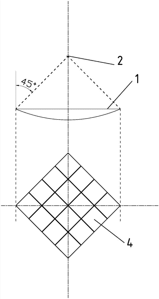
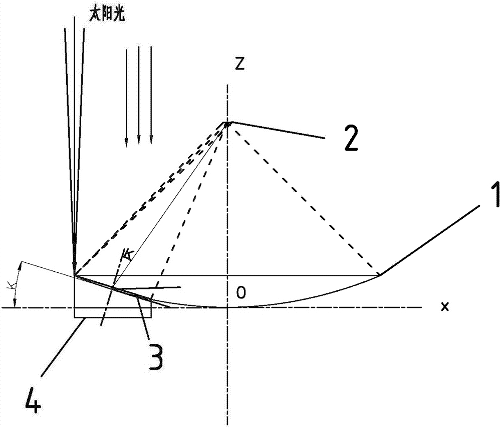
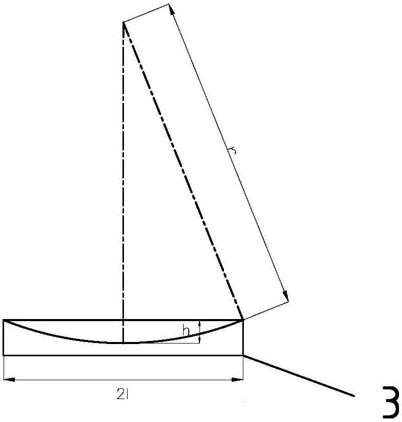
[0079] Such as Figure 1-Figure 3 As shown, a solar dish type condenser lens system includes a solar dish type condenser lens 1 and a heat absorber 2 located near the focal plane of the solar dish type condenser lens 1. The solar dish type condenser lens 1 is spliced ​​by M spherical mirrors 3 The reflecting surface of the spherical mirror 3 is a quadrilateral curved surface, the four vertices of the quadrilateral curved surface are located on the same paraboloid of revolution, and the orthographic projections of the M spherical mirrors 3 on the tangent plane passing through the vertices of the paraboloid of revolution are all squares. And the area is equal.

[0080] The orthographic projection of the spherical mirror 3 on the tangent plane passing through the vertices of the spherical mirror 3 is quadrilateral, that is, the orthographic projection of the splicing line between a certain spherical mirror 3 and its adjacent spherical mirror 3 on the tangent plane passing the vertic...

Embodiment 2

[0112] A method for designing a solar dish type condenser lens system has the following steps:

[0113] 1) Calculate S, the S satisfies the following relationship:

[0114] W=DNI*S*μ*a 1 *a 2 *a 3 ,

[0115] Where, S is the equivalent area of ​​the sum of the areas of M of the squares 4, m 2 ;

[0116] W is the rated power of the solar dish condenser 1, W, in this embodiment, W=6000W;

[0117] μ is the light interception efficiency of the solar dish type condenser lens 1, since α=45°, the solar dish type condenser lens 1 has the maximum light interception efficiency, μ=0.9;

[0118] DNI is the direct solar constant, W / m 2 , DNI=900W / m 2 ;

[0119] a 1 Is the reflectivity of the spherical mirror 3, a 1 =0.93;

[0120] a 2 Is the conversion efficiency of heat sink 2, a 2 = 0.4 (determined by heat sink 2, such as about 15% of monocrystalline silicon in photovoltaic solar panels);

[0121] a 3 Is the atmospheric absorption coefficient (air takes away the heat near the focal plane during the foc...


PUM


Abstract

The present invention discloses a solar energy disc-type collection lens system. The system comprises a solar energy disc-type collection lens and a heat absorber located near the focal plane of the solar energy disc-type collection lens, the solar energy disc-type collection lens is formed by splicing M spherical mirrors, the reflection surfaces of the spherical mirrors are quadrangle curved surfaces, the four vertexes of the quadrangle curved surfaces are located at the same paraboloid of revolution, and the orthographic projections of the M spherical mirrors on tangent planes passing through the vertexes of the paraboloid of revolution are square and have the same area. The present invention discloses the method of the solar energy disc-type collection lens system. The spherical mirrors with easy processing are processed to reduce the number of the reflection mirror units and the number of manufacturing dies, reduce the processing and manufacturing cost and improve the optical precision; the deformation errors are little and optics stability is high caused by the environment and other factors; and moreover, the light spot uniformity is high, and the shape is easy to regulate.

Description

Technical field [0001] The invention relates to the technical field of photothermal power generation, in particular to a solar dish type condenser lens system and a design method thereof. Background technique [0002] The mirror surface of the existing disc condenser mainly adopts a rotating paraboloid. Due to the limitation of the processing technology, the paraboloid must be divided into multiple units. These units are divided into arrays according to the symmetry. Each group has several units and requires several mirrors. For manufacturing molds, the more units are divided, the better the optical properties of the condenser lens, but the number of lens manufacturing molds required increases; at the same time, the light interception loss caused by the gaps in the edge of the lens unit increases. In terms of processing technology, the mirror surface of each lens unit is hyperboloid. The entire optical system forms a fixed-shaped spot on the absorber plane. [0003] The existing ...

Claims


Application Information

Patent Timeline
Patent Type & Authority Applications(China)
IPC IPC(8): G02B19/00G02B27/00
CPCG02B19/0019G02B19/0042G02B27/0012
Inventor 宋海峰王振声
Owner DALIAN GREAT OCEAN NEW ENERGY DEV
Why Eureka
Try Eureka