
Vehicle fault remote diagnosis system and method

A technology for remote diagnosis and vehicle failure, applied in general control systems, control/adjustment systems, test/monitoring control systems, etc., can solve problems such as unresolved solutions, save development costs, reduce maintenance costs and man-hours, and improve The effect of maintenance efficiency

Inactive Publication Date: 2017-10-20
SOUEAST
View PDF9 Cites 73 Cited by
  • Summary
  • Abstract
  • Description
  • Claims
  • Application Information

AI Technical Summary

Problems solved by technology

[0005] The existing public literature on remote diagnosis of vehicle faults has not come up with a complete set of solutions: how to solve remote diagnosis of vehicle faults, how to ensure the timeliness of remote diagnosis, and how to reduce the impact of remote diagnosis on the normal operation of the vehicle. Ensure vehicle safety

Method used


Image

  • Vehicle fault remote diagnosis system and method
  • Vehicle fault remote diagnosis system and method
  • Vehicle fault remote diagnosis system and method

Examples


Embodiment 1

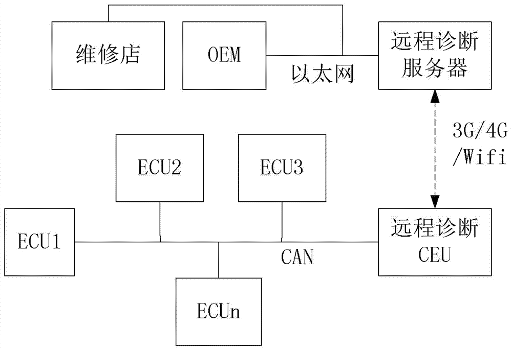
[0050] key points please refer to figure 1 , a vehicle fault remote diagnosis system, including a remote diagnosis ECU and a remote diagnosis server, the remote diagnosis ECU access to the CAN bus of the vehicle, and carry out data transmission with the remote diagnosis server through a wireless communication method; the wireless communication method Including 3G / 4G / wifi;

[0051] The remote ECU collects fault information stored on the ECU of the vehicle, and collects real-time dynamic information of the vehicle according to user needs. Interaction; the ECU on the vehicle refers to all other ECUs on the vehicle except the remote diagnosis ECU;

[0052] The remote diagnosis server stores the ECU diagnosis database, vehicle type, and vehicle VIN code information, and sends the collected user's diagnosis request to the remote diagnosis ECU, and converts the fault data returned by the remote diagnosis ECU into a diagnosis result Send back to the user; the OEM user and the vehicl...

Embodiment 2

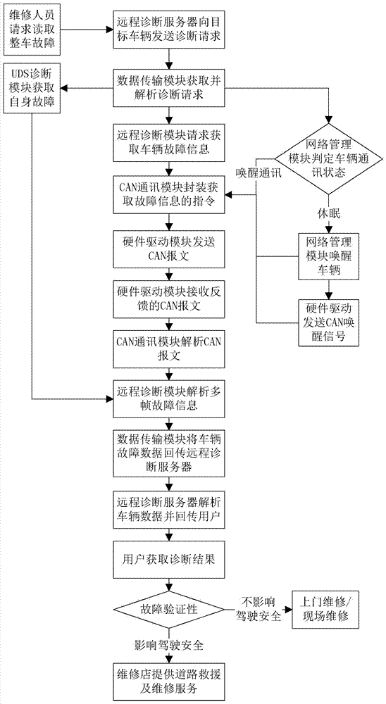
[0075] A remote diagnosis method for vehicle faults, connecting a remote diagnosis ECU to the CAN bus of the vehicle, and performing data transmission with a remote diagnosis server through wireless communication;

[0076] The remote ECU collects fault information stored on the ECU of the vehicle, and collects real-time dynamic information of the vehicle according to user needs. Interaction; the ECU on the vehicle refers to all other ECUs on the vehicle except the remote diagnosis ECU;

[0077] The remote diagnosis server stores the ECU diagnosis database, vehicle type, and vehicle VIN code information, and sends the collected user's diagnosis request to the remote diagnosis ECU, and converts the fault data returned by the remote diagnosis ECU into a diagnosis result Send back to the user; the OEM user and the vehicle maintenance shop user log in the remote diagnosis server through the client to analyze and process the fault.

[0078] key points please refer to image 3 , th...


PUM


Abstract

The invention provides a vehicle fault remote diagnosis system, which includes a remote diagnosis ECU and a remote diagnosis server. The remote diagnosis ECU is connected with a CAN bus of a vehicle. The remote ECU collects fault information stored in ECUs on the vehicle and collects real-time dynamic information of the vehicle according to the needs of a user. Meanwhile, the remote diagnosis ECU executes the real-time information interaction between the vehicle and the remote diagnosis server. The ECUs on the vehicle refer to all the other ECUs on the vehicle except the remote diagnosis ECU. The remote diagnosis server stores an ECU diagnosis database, the vehicle model and the vehicle VIN code information, sends the collected diagnosis request of the user to the remote diagnosis ECU, and converts fault data returned by the remote diagnosis ECU into a diagnosis result which is sent to the user. According to the invention, a faulty vehicle can be remotely diagnosed in real time, the influence of the remote diagnosis on the normal running of the vehicle is eliminated, and the vehicle driving safety is ensured.

Description

【Technical field】 [0001] The invention relates to a vehicle fault remote diagnosis system and method. 【Background technique】 [0002] The existing on-board diagnostic system needs to use a diagnostic instrument to perform on-site fault diagnosis on the vehicle. There are generally two types of diagnostic instruments, one is handheld, which is an independent device with a display screen, and the other is a hardware box connected to the vehicle. The software is installed on the notebook, and the software and hardware boxes on the notebook are combined as a set of diagnostic instruments. Using a diagnostic instrument for fault diagnosis cannot confirm the vehicle fault at the first time when the fault occurs, and the vehicle needs to be moved to a repair shop before using the diagnostic instrument for fault diagnosis. The timeliness of fault repair is poor and the maintenance time of the user is wasted. [0003] The "Remote Real-time Diagnosis Method for Vehicle Faults" with t...

Claims


Application Information

Patent Timeline
Patent Type & Authority Applications(China)
IPC IPC(8): G05B23/02
CPCG05B23/027
Inventor 林华霖金小红胡红兵许苘
Owner SOUEAST
Learn More