
Low-speed gearbox and double-fed wind turbine optimization design method based on direct-current transmission

A technology of wind turbines and direct current transmission, applied in design optimization/simulation, calculation, electrical digital data processing, etc., can solve problems such as rotor current increase, gearbox speed increase ratio reduction, gearbox volume, cost increase, etc., to achieve Effects of volume reduction, failure rate reduction, and cost reduction

Active Publication Date: 2017-10-20
QUFU NORMAL UNIV
View PDF8 Cites 4 Cited by
  • Summary
  • Abstract
  • Description
  • Claims
  • Application Information

AI Technical Summary

Problems solved by technology

However, the reduction of the gearbox speed ratio and the reduction of the synchronous speed will lead to an increase in the current of the DFIG stator and rotor, and an increase in the volume and cost of the gearbox. For this reason, the optimization design and control problems of the entire system must be solved.

Method used


Image

  • Low-speed gearbox and double-fed wind turbine optimization design method based on direct-current transmission
  • Low-speed gearbox and double-fed wind turbine optimization design method based on direct-current transmission
  • Low-speed gearbox and double-fed wind turbine optimization design method based on direct-current transmission

Examples


Embodiment

[0110] Taking the doubly-fed wind turbine produced by a certain company as an example, its main parameters are: P=3MW, V s =1650V (stator voltage), I s =600A, I r =608A,n 1N =1000rpm, n p =3, gearbox speed-up ratio N=80, L m =99mH,L s =99.99mH; gearbox cost C g1 = 220,000 Euros (Euro), DFIG cost C t1 = 60,000 Euros, converter cost C c1 = 86,700 euros, the total cost of the three parties C s1 = 366,700 euros; k 0 = 0,k 1 =0.2,k 2 =0.35,k 3 =0.45, β=1.01, α=0.0884.

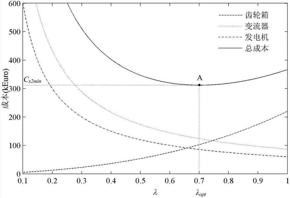
[0111] First, draw the optimized gearbox cost C according to formula (18), formula (20), formula (22) and formula (6) g2 -λ curve, DFIG cost C t2 -λ curve, DC converter cost C c2 -λ curve, the total cost C of the above three in the doubly-fed wind turbine s2 -λ curves, such as figure 2 shown. from figure 2 As can be seen in , the cost of the gearbox C g2 Gradually decreases as λ decreases; the cost of the converter and DFIG (C c2 、C t2 ) gradually increases with the decrease of λ; the total c...


PUM


Abstract

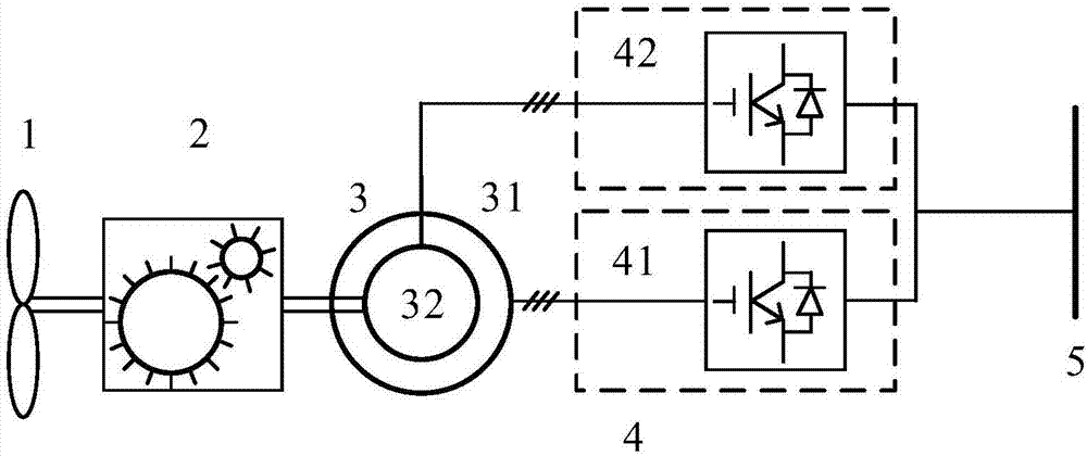
The invention relates to a low-speed gearbox and double-fed wind turbine optimization design method based on direct-current transmission, and belongs to the field of wind power. According to the method, a double-fed wind power generation system topology structure is adopted to conduct optimization design and control over a double-fed wind turbine comprising a gearbox, a double-fed induction generator (DFIG) and a direct-current transformer. The method comprises the steps that the ratio of the stator current, before optimization, of the DFIG to the stator current, after optimization, of the DFIG, the ratio of the rotor current, before optimization, of the DFIG to the rotor current, after optimization, of the DFIG, the ratio of the total current before optimization to the total current after optimization and the ratio of the total current, before optimization, of the direct-current transformer to the total current, after optimization, of the direct-current transformer are solved by adopting a stator flux vector directional control strategy; the total cost C<s2> of the double-fed wind turbine after optimization is solved; wind turbine optimization design parameters are solved; and a C<s2>-lambda curve is drawn according to a C<s2> formula, a minimum value of C<s2> and an optimum value of lambda are solved, and then the gearbox speed increasing ratio after optimization and the stator current, the rotor current, the synchronous revolving speed and the stator rated frequency of the DFIG are obtained, wherein lambda represents the ratio of the gearbox speed increasing ratio before optimization to the gearbox speed increasing ratio after optimization. According to the method, the gearbox speed increasing ratio is decreased, the failure rate can be decreased, the cost can be reduced, and the system operation reliability can be improved.

Description

technical field [0001] The invention relates to an optimal design method, in particular to an optimal design method for a low-speed gearbox doubly-fed wind turbine based on DC transmission, and belongs to the technical field of wind power generation. Background technique [0002] The doubly-fed wind power generation system is mainly composed of a wind turbine, a gearbox, a doubly-fed wind generator (DFIG), and a converter. DFIG is a high-speed, small-sized generator. Since the wind turbine operates at low speed, a speed-up gearbox with a high speed-up ratio is usually used to increase the low speed of the wind turbine to a high-speed rotor speed. The higher the speed-up ratio of the gearbox, the smaller the volume and cost of DFIG; but the larger the speed-up ratio of the gearbox, the higher the volume and cost of the gearbox, the greater the energy loss and failure rate, and the reliability of the whole system worse. The main loss of the doubly-fed wind power generation s...

Claims


Application Information

Patent Timeline
Patent Type & Authority Applications(China)
IPC IPC(8): G06F17/50
CPCG06F30/20Y02E60/00
Inventor 闫绍敏蔡彬褚晓广
Owner QUFU NORMAL UNIV
Learn More