
Packaging component and manufacturing method thereof

A technology of packaging components and manufacturing methods, which is applied in the direction of electrical components, semiconductor devices, circuits, etc., can solve the problem that the angle of light output and the uniformity of light output cannot meet the requirements, the thickness and uniformity of the dam are difficult to control, and the installation process of the dam is complicated. Problems, to achieve the requirements of reducing the operating accuracy, ensure the light angle and light color uniformity, and facilitate the effect of mass production

Pending Publication Date: 2017-10-20
深圳市科艺星光电科技有限公司
View PDF12 Cites 6 Cited by
  • Summary
  • Abstract
  • Description
  • Claims
  • Application Information

AI Technical Summary

Problems solved by technology

[0003] The purpose of the present invention is to provide a packaged component and its manufacturing method to solve the problems in the prior art that the installation process of the dam is complicated and the thickness and uniformity of the dam are not easy to control, resulting in the failure of the light output angle and light uniformity. Asked technical questions

Method used


Image

  • Packaging component and manufacturing method thereof
  • Packaging component and manufacturing method thereof
  • Packaging component and manufacturing method thereof

Examples


Embodiment Construction

[0028] In order to make the technical problems, technical solutions and beneficial effects to be solved by the present invention clearer, the present invention will be further described in detail below in conjunction with the accompanying drawings and embodiments. It should be understood that the specific embodiments described here are only used to explain the present invention, not to limit the present invention.

[0029] It should be noted that when an element is referred to as being “fixed” or “disposed on” another element, it may be directly on the other element or be indirectly on the other element. When an element is referred to as being "connected to" another element, it can be directly connected to the other element or indirectly connected to the other element.

[0030] It is to be understood that the terms "length", "width", "top", "bottom", "front", "rear", "left", "right", "vertical", "horizontal", "top" , "bottom", "inner", "outer" and other indicated orientations...


PUM


Abstract

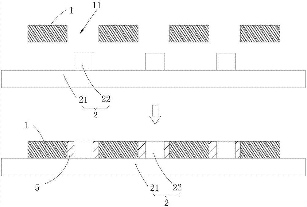
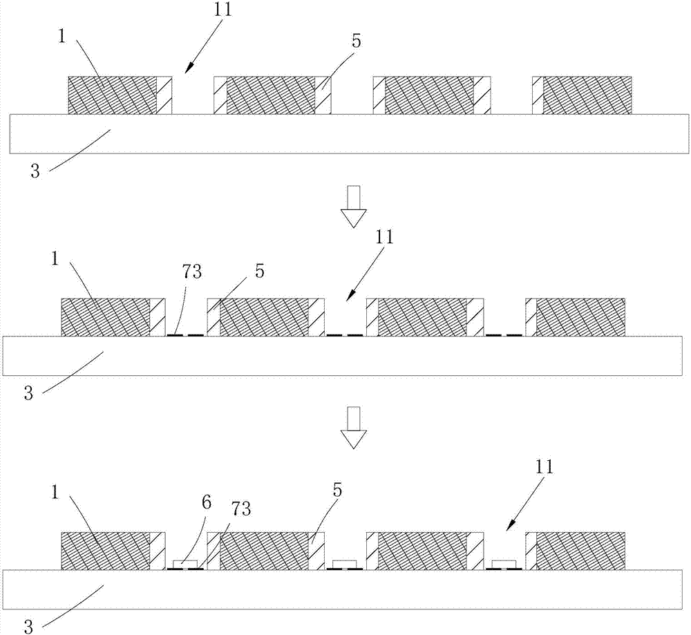
The invention provides a manufacturing method of a packaging component. The manufacturing method comprises the steps of dam installation, wafer fixing, packaging colloid injecting and packaging and mold removing. The invention further provides a packaging component which is manufactured by applying the packaging component manufacturing method. The packaging component is used for being mounted on a circuit board. The packaging component comprises a wafer, a bonding pad assembly arranged at one side of the wafer, packaging colloid packaging outside the wafer and the bonding pad assembly and a dam enclosing outside the packaging colloid, wherein the bonding pad assembly comprises a positive bonding pad, a negative bonding pad and metal pieces used for connecting the circuit board and the positive bonding pad and the negative bonding pad, the metal pieces are connected with the positive bonding pad and the negative bonding pad in a one-to-one correspondence manner, and the area of the metal piece is greater than or equal to the area of the positive bonding pad or the negative bonding pad. Batch production is performed by adopting cooperation of various molds, so that mass production can be carried out more conveniently. In addition, the positions of the wafer and the packaging colloid relative to the dam can be better limited, and the light emitting angle and the light color uniformity of an optical design are effectively ensured.

Description

technical field [0001] The invention belongs to the technical field of semiconductor packaging, and more specifically relates to a packaging component and a manufacturing method thereof. Background technique [0002] CSP (Chip Scale Package) packaging is chip-level packaging, which is a way of semiconductor chip packaging. CSP LED packaging technology has the advantages of better heat dissipation performance, simplified substrate and greatly improved product reliability. The CSP LED package in the prior art is a five-sided light-emitting structure without a substrate and a bracket. In some light source application fields, there are high requirements for the light output angle and light output uniformity, such as mobile phone flashlights and car lighting. , stage lights, high bay lights and flashlight lights and other fields, and some products in these fields do not require high-power light sources. In the prior art, dams are generally used to solve the problems of light out...

Claims


Application Information

Patent Timeline
Patent Type & Authority Applications(China)
IPC IPC(8): H01L33/48H01L33/52
CPCH01L33/486H01L33/52H01L2933/0033H01L2933/005
Inventor 林书弘
Owner 深圳市科艺星光电科技有限公司
Learn More