A duty ratio adjustment circuit and its realization method

A technology for adjusting circuit and duty cycle, applied in electrical components, generating electrical pulses, pulse technology and other directions, can solve the clock duty cycle deviation, poor resistance to voltage, temperature changes, and it is difficult for oscillator circuits to output 50% of the Problems such as empty ratio signal

Active Publication Date: 2020-10-16
SHANGHAI ADVANCED RES INST CHINESE ACADEMY OF SCI
View PDF5 Cites 0 Cited by
  • Summary
  • Abstract
  • Description
  • Claims
  • Application Information

AI Technical Summary

Problems solved by technology
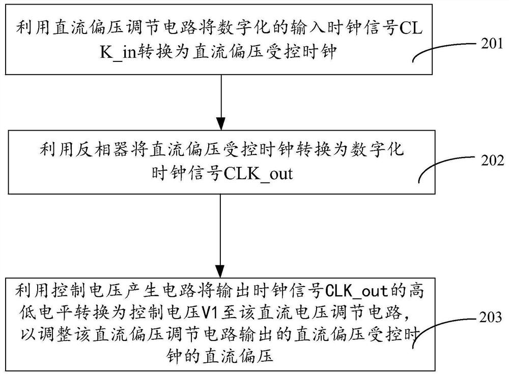
However, in actual circuits, many reasons will cause the clock duty cycle to deviate from 50%. For example, due to the difference in driving capability between PMOS and NMOS, and the difference in the distribution of interconnect parasitic capacitance, it is difficult for the oscillator circuit to output a 50% duty cycle. ratio signal
[0003] It can be seen that the existing duty cycle regulation is either poor in resistance to voltage and temperature changes, or the design is relatively complicated, so how to generate a 50% duty cycle clock suitable for high-speed circuit systems has become a hot issue that needs to be solved urgently

Method used


Image

  • A duty ratio adjustment circuit and its realization method
  • A duty ratio adjustment circuit and its realization method

Examples


Embodiment Construction

[0025] The implementation of the present invention is described below through specific examples and in conjunction with the accompanying drawings, and those skilled in the art can easily understand other advantages and effects of the present invention from the content disclosed in this specification. The present invention can also be implemented or applied through other different specific examples, and various modifications and changes can be made to the details in this specification based on different viewpoints and applications without departing from the spirit of the present invention.

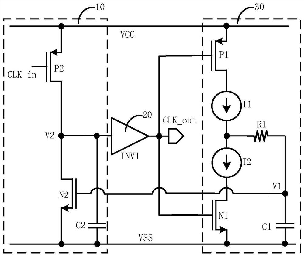
[0026] figure 1 It is a circuit structure diagram of a duty cycle adjusting circuit of the present invention. like figure 1 As shown, a duty ratio adjustment circuit of the present invention includes: a DC voltage adjustment circuit 10 , an inverter 20 and a control voltage generation circuit 30 .

[0027] Wherein, the DC voltage regulating circuit 10 includes a second PMOS transistor P2,...


PUM


Abstract

The invention discloses a duty ratio adjusting circuit and an implementation method thereof. The duty ratio adjusting circuit comprises a DC bias voltage adjusting circuit used for converting a digitalized input clock signal CLK _ in into a DC bias voltage controlled clock; a phase inverter used for converting the DC bias voltage controlled clock into a digitalized clock signal CLK _ out; a control voltage generation circuit used for generating a control voltage under the control of high and low levels of the output clock signal CLK _ out, wherein the control voltage is connected to the DC bias voltage adjusting circuit to adjust the DC bias voltage of the DC bias voltage controlled clock output by the DC bias voltage adjusting circuit. By adoption of the duty ratio adjusting circuit, the duty ratio adjusting circuit capable of adjusting the duty ratio of signals to 50% is realized.

Description

technical field [0001] The invention relates to an adjusting circuit and its realization method, in particular to a duty ratio adjustment circuit and its realization method. Background technique [0002] In modern integrated circuits, a 50% duty cycle clock plays a vital role. However, in actual circuits, many reasons will cause the clock duty cycle to deviate from 50%. For example, due to the difference in driving capability between PMOS and NMOS, and the difference in the distribution of interconnect parasitic capacitance, it is difficult for the oscillator circuit to output a 50% duty cycle. than signal. [0003] It can be seen that the existing duty ratio adjustments are either poor in resistance to voltage and temperature changes, or the design is relatively complicated, so how to generate a 50% duty ratio clock suitable for high-speed circuit systems has become a hot issue that needs to be solved urgently. [0004] Therefore, it is really necessary to provide a duty ...

Claims


Application Information

Patent Timeline
Patent Type & Authority Patents(China)
IPC IPC(8): H03K3/017H03K3/011
CPCH03K3/011H03K3/017
Inventor 梅年松张钊锋
Owner SHANGHAI ADVANCED RES INST CHINESE ACADEMY OF SCI
Why Eureka
Try Eureka