Current fluctuation control method for reducing switched reluctance motor current chopping control mode

A technology of current chopping and control mode, applied in the direction of AC motor control, control system, general control strategy, etc., to achieve the effect of simple implementation, improved rapidity and accuracy, and improved control accuracy

Active Publication Date: 2022-02-22
TAIYUAN UNIV OF TECH
View PDF5 Cites 0 Cited by
  • Summary
  • Abstract
  • Description
  • Claims
  • Application Information

AI Technical Summary

Problems solved by technology

[0003] In view of the above existing problems, the present invention proposes a way to reduce the current fluctuation of the switched reluctance motor under the current chopping control mode, so as to realize the adaptive adjustment of the PWM duty cycle when the current chopping is turned on at different speeds and loads , which solves the problem that the current fluctuation exceeds the upper and lower limits of chopping under the current chopping control mode

Method used


Image

  • Current fluctuation control method for reducing switched reluctance motor current chopping control mode
  • Current fluctuation control method for reducing switched reluctance motor current chopping control mode
  • Current fluctuation control method for reducing switched reluctance motor current chopping control mode

Examples


Embodiment Construction

[0047] An embodiment of the present invention will be further described below in conjunction with the accompanying drawings.

[0048] Step 1: Detect the position signal of the rotor of the switched reluctance motor through the position sensor, distinguish the commutation section and the separate conduction section according to the position signal, and calculate the actual speed of the motor by the time it takes to rotate through a fixed angle;

[0049] Step 2, setting the reference current according to the difference between the actual speed of the motor and the target speed;

[0050] Step 3, collect the actual current value of the phase winding through the Hall current sensor;

[0051] Step 4, according to the difference between the actual current of the winding and the given current, determine the PWM duty cycle when the winding is turned on next time.

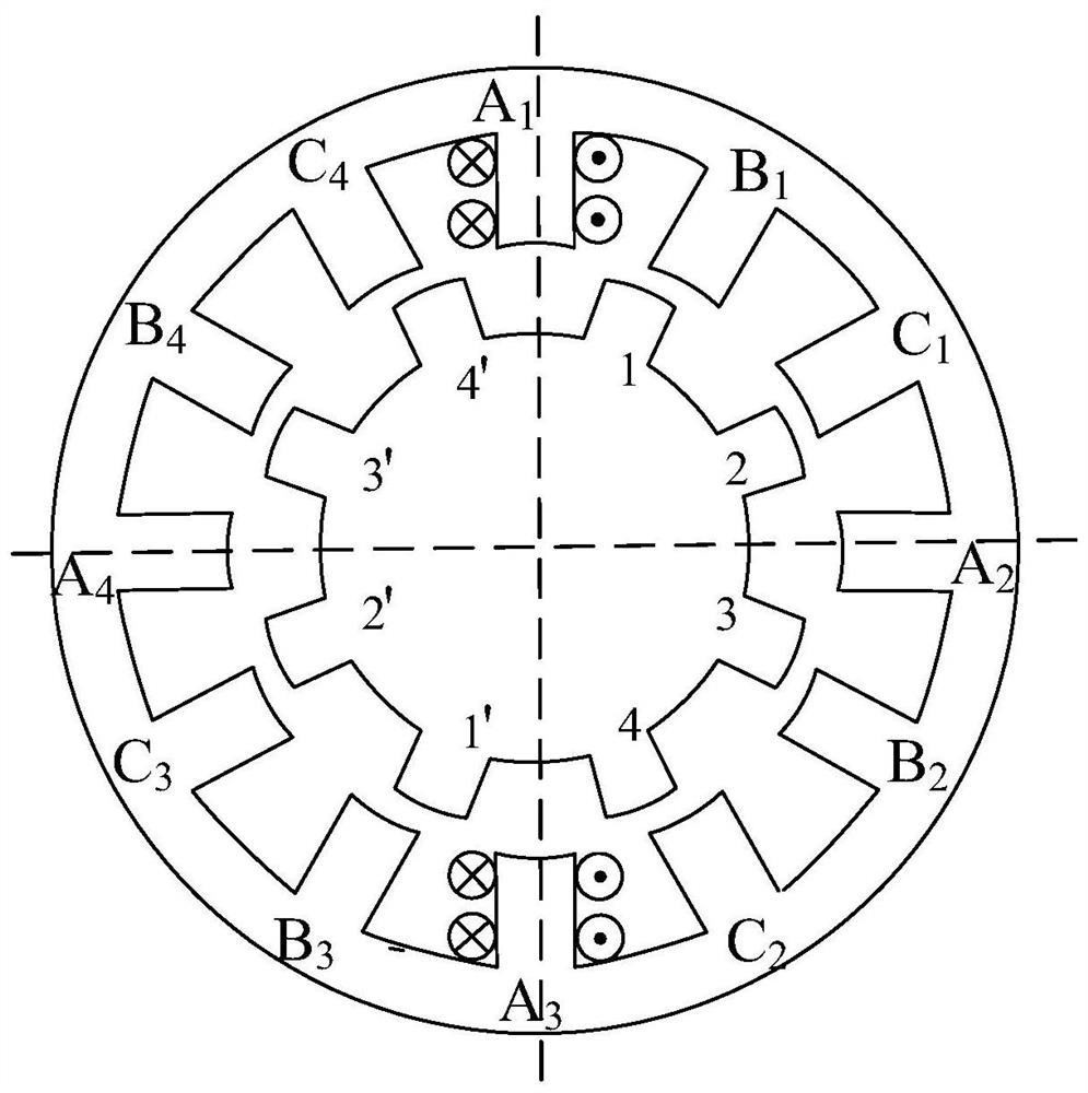
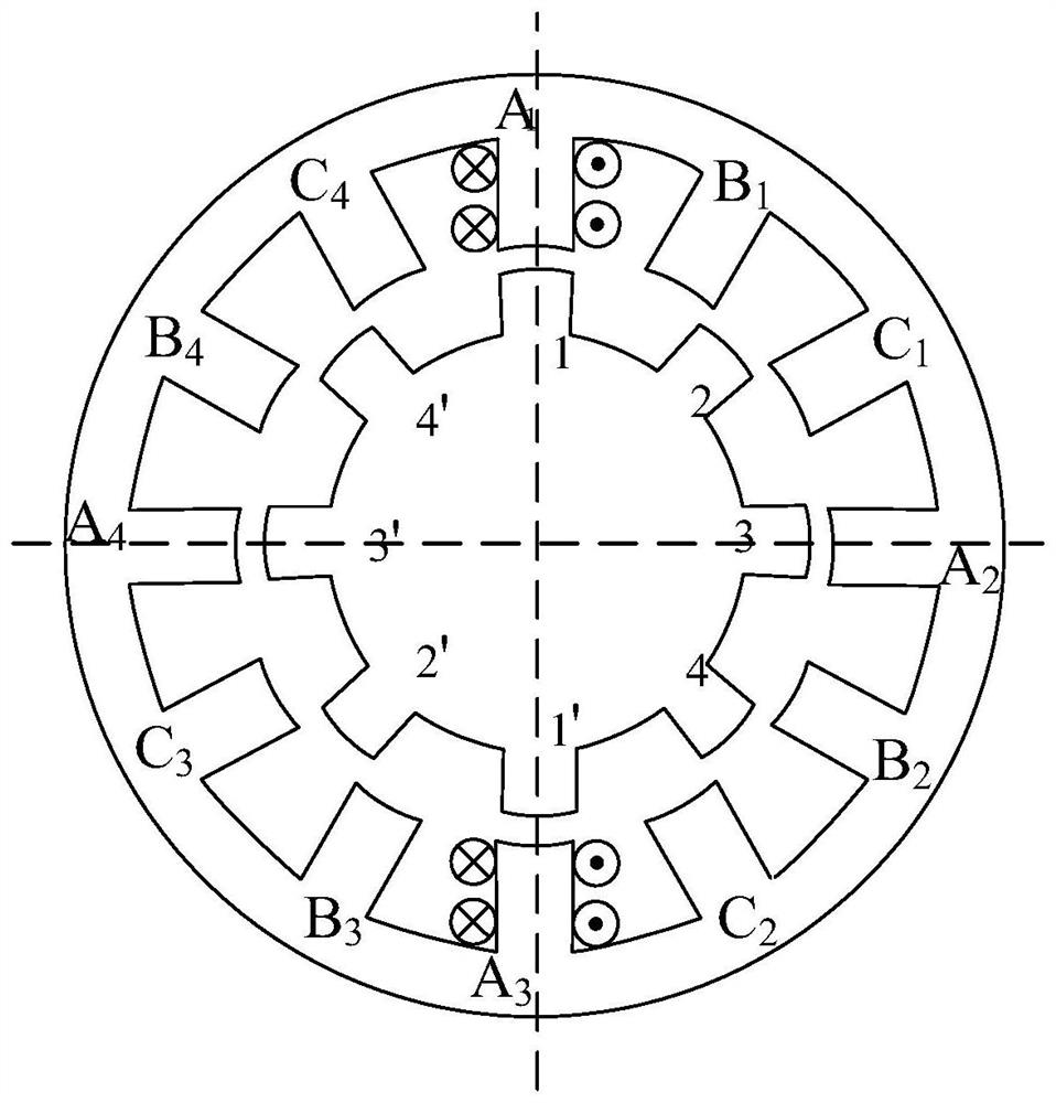
[0052] In step 1 of this embodiment, a three-phase 12 / 8-pole switched reluctance motor is used as a specific embodiment, ...


PUM


Abstract

A control method for reducing current fluctuations of switched reluctance motors under current chopping control, suitable for switched reluctance motors with various phase numbers and structures under the non-inductive model, according to the position sensor signal, a conduction period is divided into Commutation section and separate conduction section; the given current determined according to the given speed and the actual speed of the motor calculated by the position sensor; the winding current of each phase is collected by the Hall current sensor; The actual current of the phase segment and the individual conduction segment adjusts the PWM duty cycle of the commutation segment and the individual conduction segment respectively; the input of the controller is the speed difference, the actual current of the winding, and the position signal, and the output is the PWM duty cycle. In this way, the control of the power converter is realized, and the power converter controls the power on and off of the switched reluctance motor to control the motor speed. The invention improves the steady-state characteristics of the switched reluctance motor, increases the steady-state operation efficiency, and reduces the output torque ripple of the motor.

Description

technical field [0001] The invention relates to a method for suppressing the current fluctuation of a switched reluctance motor, which is suitable for switched reluctance motors with various phase numbers and structures under a non-inductance model. Background technique [0002] Switched reluctance motor has attracted wide attention in the transmission system due to its simple structure, low manufacturing cost, good controllability, and frequent forward and reverse rotation. Due to the high reliability and simple implementation of the current chopper control method, it has become a control method commonly used in switched reluctance motors in practical applications. However, since the current chopper control belongs to the hysteresis control, the winding current of the switched reluctance motor fluctuates beyond the upper and lower limits of the chopper. Reaching about twice the reference current, this will increase the power loss of the transmission line in the system and ...

Claims


Application Information

Patent Timeline
Patent Type & Authority Patents(China)
IPC IPC(8): H02P25/08H02P23/00
CPCH02P23/0004H02P25/08
Inventor 曲兵妮田德翔宋建成赵勇
Owner TAIYUAN UNIV OF TECH
Why Eureka
Try Eureka