Autogenous mill/semi-autogenous mill discharging flow distribution device

A semi-autogenous mill and diverting device technology, which is applied in grain processing and other directions, can solve the problems of impact and wear of the ore discharge diverting device, affecting output, and large processing capacity, so as to facilitate installation and disassembly, improve screening efficiency, and reduce production costs. Effect

Pending Publication Date: 2017-10-24
中冶北方(大连)工程技术有限公司
View PDF0 Cites 0 Cited by
  • Summary
  • Abstract
  • Description
  • Claims
  • Application Information

AI Technical Summary

Problems solved by technology

The autogenous mill / semi-autogenous mill usually has a large processing capacity, and the discharged pulp has a high concentration and contains large particles. The impact and wear on the ore discharge and diversion device are very serious. After the ore discharge and diversion device is worn out, the autogenous mill needs to be stopped for maintenance, reducing Increased equipment operating rate, affecting output, and increasing operating costs of the dressing plant
In addition, since the autogenous mill / semi-autogenous mill is discharging during rotation, the ore discharge and diversion device often feeds unevenly to the vibrating screen, which affects the screening efficiency and processing capacity of the vibrating screen. production bottleneck

Method used


Image

  • Autogenous mill/semi-autogenous mill discharging flow distribution device
  • Autogenous mill/semi-autogenous mill discharging flow distribution device
  • Autogenous mill/semi-autogenous mill discharging flow distribution device

Examples


Embodiment Construction

[0024] The present invention will be further described below in conjunction with accompanying drawing.

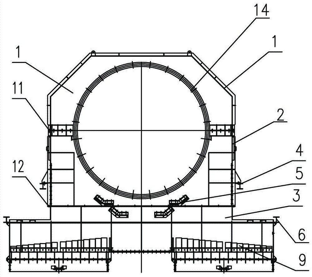
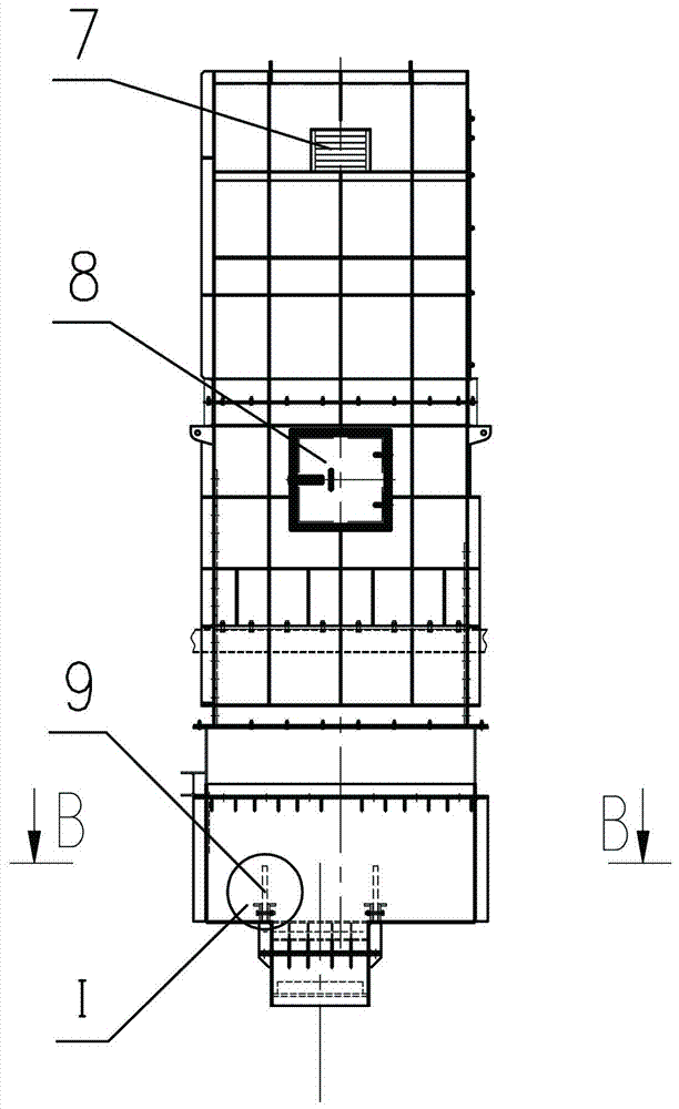
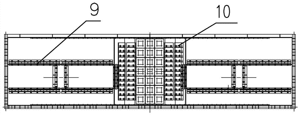
[0025] Such as Figure 1-Figure 4 As shown, a kind of autogenous mill / semi-autogenous mill discharge and diversion device of the present invention includes the autogenous mill / semi-autogenous mill discharge opening 14, and is characterized in that: it also includes an upper end cover 1, a middle collecting mechanism And the lower distribution mechanism, the design of the split structure can realize the convenience of transportation, installation and disassembly, and it is convenient to adjust the distribution plate 9 and replace the liner of the deflector 5

[0026] The middle collection mechanism includes a collection box 2 fixedly connected to the upper end cover 1 by bolts and flanges 11, and deflectors 5 fixed on both ends of the bottom of the collection box 2 by bolts. The plate 5 is located below the discharge port 14 of the autogenous mill / semi-autogenous mill and a...


PUM


Abstract

The invention discloses an autogenous mill / semi-autogenous mill discharging flow distribution device. The device comprises an autogenous mill / semi-autogenous mill discharging outlet, and further comprises an upper end cover, a middle aggregate mechanism and a lower flow distribution mechanism. The middle aggregate mechanism comprises an aggregate box and a flow guiding plate. The lower flow distribution mechanism comprises a flow distribution base and flow distribution plate sets arranged on the left and right sides of the bottom of the flow distribution base; the upper end cover, and the middle aggregate mechanism and the lower flow distribution mechanism are supported and suspended on a platform beam of an autogenous mill / semi-autogenous mill through connecting supports outside the two sides of the middle aggregate box and connecting hanging brackets outside the two sides of the flow distribution base. The autogenous mill / semi-autogenous mill discharging flow distribution device has the advantages that by arranging the flow guiding plate and flow distribution plates, uniform discharging of the discharging region is achieved, it is ensured that a vibration screen receives materials uniformly, the screening efficiency and the processing capability are improved, and the production cost is lowered; the flow distribution plates are convenient to transport, assemble, disassemble and adjust, and a lining plate is replaced; by arranging an exhaust window and a viewport, convenience is brought to operation and production of post holders.

Description

technical field [0001] The invention relates to the technical field of supporting equipment for grinding and grading in the mineral processing industry, in particular to a discharge and flow device for an autogenous mill / semi-autogenous mill. Background technique [0002] With the development of large-scale iron ore concentrators, autogenous / semi-autogenous grinding technology has been widely used, and the technology is becoming more and more mature. It has the characteristics of advanced and reliable process, large and efficient equipment, low investment and quick results, and short grinding process. The wet semi-autogenous grinding process is especially used more due to its strong adaptability to changes in ore properties, raw ore containing mud, and ore with a high water content. [0003] Autogenous mill / semi-autogenous mill usually adopts vibrating screen as the classification equipment. One autogenous mill / semi-autogenous mill is usually equipped with two vibrating scre...

Claims


Application Information

Patent Timeline
IPC IPC(8): B02C23/10B02C23/00
CPCB02C23/00B02C23/10
Inventor 常校亮周慧
Owner 中冶北方(大连)工程技术有限公司
Why Eureka
Try Eureka