Cleaning cabinet for vehicle rubber and plastic part production

A technology for parts and cleaning cabinets, which is applied to cleaning methods using liquids, cleaning methods using gas flow, cleaning methods and utensils, etc., which can solve problems such as pollution, unsatisfactory cleaning effects, and waste of manpower. The environment is comfortable, easy to promote and use, and the effect of saving manpower and material resources

Inactive Publication Date: 2017-10-24
枞阳县金源汽车零部件有限公司
View PDF9 Cites 5 Cited by
  • Summary
  • Abstract
  • Description
  • Claims
  • Application Information

AI Technical Summary

Problems solved by technology

[0002] With the development of the times, people use cars more and more widely. In the production process of auto parts, it is necessary to clean auto parts, such as engine cylinder blocks, cylinder heads, pistons, connecting rods, crankshafts and gearbox shells. Body, shaft, bearing, gear, etc., but the cleaning of rubber and plastic parts is not perfect. Most of the cleaning of auto parts adopts the traditional cleaning method, which has low cleaning efficiency, wastes energy and manpower, and is long-term engaged in this kind of cleaning. Harmful to health, the traditional method not only wastes cleaning fluid and is unsafe, but also easily causes pollution, the cleaning efficiency and cleaning quality are also very low, and even the problem of damage to parts occurs. At present, the existing cleaning equipment mainly uses high-temperature hot water soaking and Although the washing method improves the cleaning efficiency, the cleaning effect is still not ideal due to the complexity of auto parts and the strong adhesion of oil stains. Therefore, it is necessary to have a cleaning equipment that can solve the above problems.

Method used


Image

  • Cleaning cabinet for vehicle rubber and plastic part production
  • Cleaning cabinet for vehicle rubber and plastic part production

Examples


Embodiment Construction

[0013] The following will clearly and completely describe the technical solutions in the embodiments of the present invention with reference to the accompanying drawings in the embodiments of the present invention. Obviously, the described embodiments are only some, not all, embodiments of the present invention. Based on the embodiments of the present invention, all other embodiments obtained by persons of ordinary skill in the art without making creative efforts belong to the protection scope of the present invention.

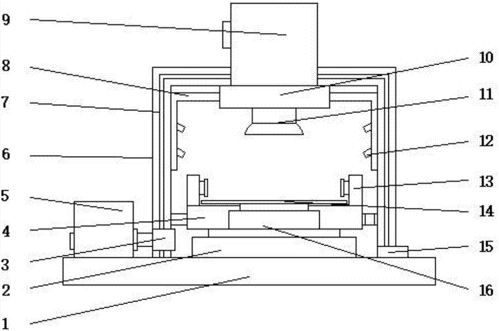
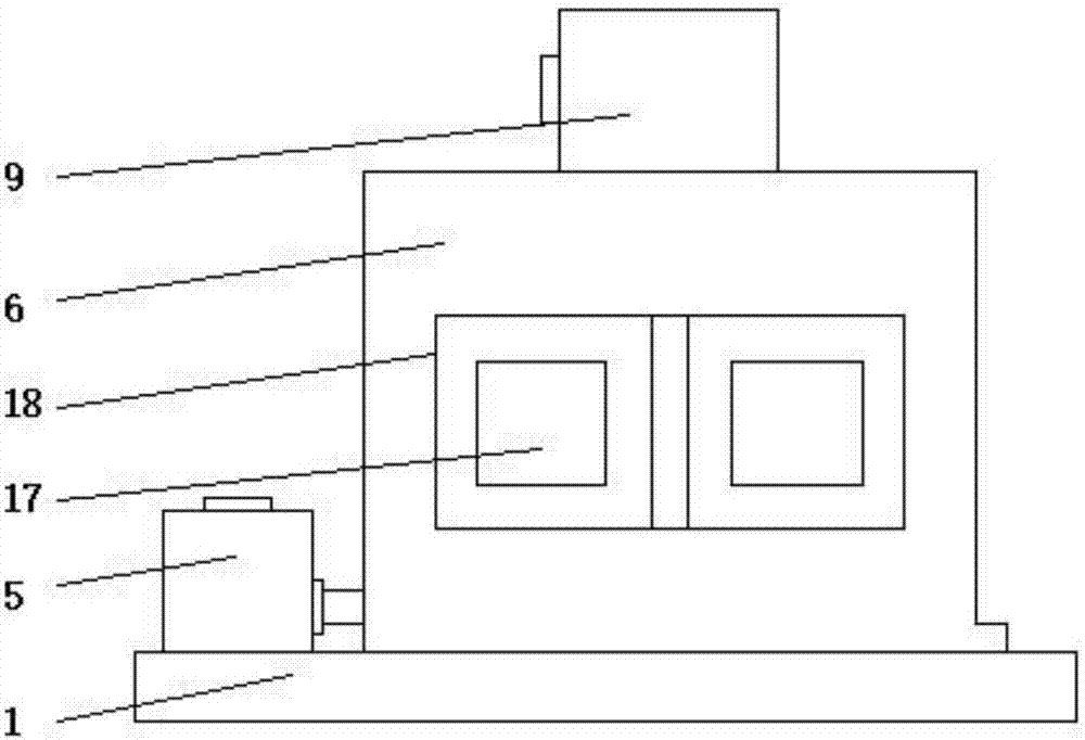
[0014] see Figure 1-2 , an embodiment provided by the present invention: a cleaning cabinet for the production of automobile rubber and plastic parts, including a base 1, a placement tank 4, a water pump 9, a main spray pipe 11 and a lifting column 16, and the top of the base 1 is installed with Cabinet 6, and a vacuum cleaner 5 is installed on the base 1 on one side of the cabinet 6, and the interior of the cabinet 6 is inlaid with a soundproof interlayer 7....


PUM


Abstract

The invention discloses a cleaning cabinet for vehicle rubber and plastic part production. The cleaning cabinet comprises a base, a placing tank, a pump, a main water spraying pipe and a lifting column; a cabinet body is mounted at the top of the base; a dust sucker is mounted on the base on one side of the cabinet body; an output end of the dust sucker communicates with the cabinet body through a dust sucking pipe; an electric rotating disc is mounted at the bottom end in the cabinet body; the lifting column is mounted in the placing tank; a ultrasonic cleaning device is mounted on the top edge of the placing tank; the pump is mounted at the top of the cabinet body; two sides of the water spraying cavity communicate with side water spraying pipes; and a sealing door is mounted on the front surface of the cabinet body. Compared with a traditional cleaning mode for cleaning rubber and plastic parts by adopting a closed cleaning cabinet, cleaning liquid generated in the cleaning process can be drained through drainage holes to prevent environmental pollution by the cleaning liquid, meanwhile, the safety of cleaning workers is guaranteed, the personal harm by the cleaning liquid is prevented, and popularization and application are convenient.

Description

technical field [0001] The invention relates to the field of auto parts production equipment, in particular to a cleaning cabinet for the production of auto rubber and plastic parts. Background technique [0002] With the development of the times, people use cars more and more widely. In the production process of auto parts, it is necessary to clean auto parts, such as engine cylinder blocks, cylinder heads, pistons, connecting rods, crankshafts and gearbox shells. Body, shaft, bearing, gear, etc., but the cleaning of rubber and plastic parts is not perfect. Most of the cleaning of auto parts adopts the traditional cleaning method, which has low cleaning efficiency, wastes energy and manpower, and is long-term engaged in this kind of cleaning. Harmful to health, the traditional method not only wastes cleaning fluid and is unsafe, but also easily causes pollution, the cleaning efficiency and cleaning quality are also very low, and even the problem of damage to parts occurs. A...

Claims


Application Information

Patent Timeline
Patent Type & Authority Applications(China)
IPC IPC(8): B08B3/12B08B3/02B08B3/10B08B5/04B08B13/00
CPCB08B3/123B08B3/022B08B3/10B08B5/04B08B13/00
Inventor 周留芳
Owner 枞阳县金源汽车零部件有限公司
Why Eureka
Try Eureka