
Die for crimping

A mold and crimping technology, applied in the direction of forming tools, manufacturing tools, metal processing equipment, etc., can solve the problems of time-consuming, increase operation complexity, labor consumption, etc., and achieve the effect of saving manpower and simple structure

Inactive Publication Date: 2017-10-24
昆山申凌精密金属工业有限公司
View PDF6 Cites 1 Cited by
  • Summary
  • Abstract
  • Description
  • Claims
  • Application Information

AI Technical Summary

Problems solved by technology

In the process of using metal materials, it is often necessary to curl them. Existing molds can only process one side of the material. If the material needs to be processed on multiple sides, it is necessary to manually adjust the position of the material, which increases the operation. The complexity is very time-consuming and labor-intensive

Method used


Image

  • Die for crimping

Examples


Embodiment Construction

[0014] In order to make the object, technical solution and advantages of the present invention more clear, the present invention will be further described in detail below in conjunction with the examples. It should be understood that the specific embodiments described here are only used to explain the present invention, not to limit the present invention.

[0015] The application principle of the present invention will be described in detail below in conjunction with the accompanying drawings.

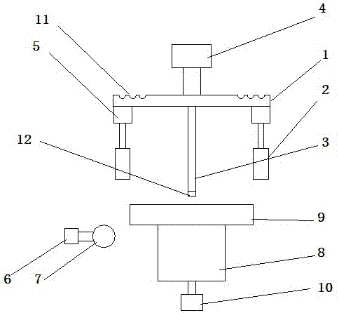
[0016] Such as figure 1 As shown, a mold for crimping includes an upper mold and a lower mold; the upper mold includes a horizontally arranged cantilever 1, a first pressure block 2 positioned at both ends of the cantilever 1, and a column 3 located in the middle of the cantilever 1, A first drive mechanism 4 is arranged above the cantilever 1, and the first briquetting block 2 is driven by a second drive mechanism 5; the first drive mechanism 4 drives the cantilever 1 and the column ...


PUM


Abstract

The invention discloses a mold for crimping, which comprises an upper mold and a lower mold; the upper mold includes a horizontally arranged cantilever, a first pressing block, and a column, and a first driving mechanism is arranged above the cantilever, and the first pressing block Driven by the second driving mechanism; the first driving mechanism drives the cantilever and the column to move down the mold; the lower mold includes a base and a second pressing block driven by the third driving mechanism, and the moving direction of the second pressing block is perpendicular to the moving direction of the cantilever , the base includes a support rod and a model plate arranged on the top of the support rod, the model plate is arranged parallel to the cantilever; the lower part of the support rod is connected with the rotating shaft of the fourth driving mechanism, and the fourth driving mechanism drives the base to rotate, and the base is close to two pressing The distance between the side walls of the blocks is equal to the distance between two compacts. The present invention uses the first pressing block to press down vertically, and then uses the second pressing block to perform horizontal pressing to realize horizontal folding, thereby completing curling. After finishing one side processing, the fourth driving mechanism is used to drive the base to rotate, thereby Realize automatic processing of multiple sides of the material, greatly saving manpower.

Description

technical field [0001] In particular the invention relates to a mold for crimping. Background technique [0002] With the rapid development of economy and science and technology, new technologies and materials in all walks of life are constantly emerging. Metal materials are also widely used in construction and other fields. In the process of using metal materials, it is often necessary to curl them. Existing molds can only process one side of the material. If the material needs to be processed on multiple sides, it is necessary to manually adjust the position of the material, which increases the operation. The complexity is very time-consuming and labor-intensive. Contents of the invention [0003] In view of the above problems, the present invention proposes a mold for crimping, which has a simple structure. The first pressing block is used to press down vertically. For this side, the second pressing block is used to press horizontally along the bottom surface of the m...

Claims


Application Information

Patent Timeline
Patent Type & Authority Applications(China)
IPC IPC(8): B21D37/10B21D19/12
CPCB21D37/10B21D19/12
Inventor 郭子英
Owner 昆山申凌精密金属工业有限公司
Learn More