Lifting-type working table used for cutting wood

A workbench and lifting technology, which is applied to wood processing equipment, sawing components, manufacturing tools, etc., can solve the problems of inability to adjust the height of the workbench and inconvenient cleaning

Active Publication Date: 2017-10-24
菏泽中创智慧消防器材有限公司
View PDF9 Cites 24 Cited by
  • Summary
  • Abstract
  • Description
  • Claims
  • Application Information

AI Technical Summary

Problems solved by technology

[0007] In order to overcome the shortcomings of the prior art that the height of the workbench cannot be adjusted and that it is inconvenient to clean the residual sawdust, the technical pr

Method used


Image

  • Lifting-type working table used for cutting wood
  • Lifting-type working table used for cutting wood
  • Lifting-type working table used for cutting wood

Examples


Embodiment 1

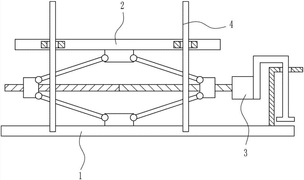
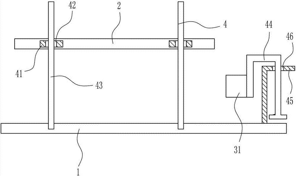
[0036] A liftable workbench for wood cutting, such as Figure 1-7 As shown, it includes a first installation base 1, a workbench 2, a lifting mechanism 3 and a guide mechanism 4, a workbench 2 is arranged above the first installation base 1, and a lifting mechanism is connected between the first installation base 1 and the workbench 2 3. A guide mechanism 4 is connected to the first installation base 1 , the workbench 2 and the lifting mechanism 3 .

Embodiment 2

[0038] A liftable workbench for wood cutting, such as Figure 1-7 As shown, it includes a first installation base 1, a workbench 2, a lifting mechanism 3 and a guide mechanism 4, a workbench 2 is arranged above the first installation base 1, and a lifting mechanism is connected between the first installation base 1 and the workbench 2 3. A guide mechanism 4 is connected to the first installation base 1 , the workbench 2 and the lifting mechanism 3 .

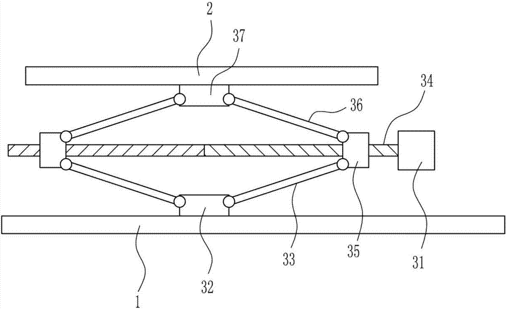
[0039] The lifting mechanism 3 includes a servo motor 31, a second mounting base 32, a first connecting rod 33, a screw rod 34, a nut 35, a second connecting rod 36 and a second mounting block 37, and the left side of the top of the first mounting base 1 is connected with The second mounting base 32, the left and right sides of the second mounting base 32 are rotationally connected with the first connecting rod 33, the upper right side of the first mounting base 1 is provided with a servo motor 31, and the servo motor 31 is conne...

Embodiment 3

[0041] A liftable workbench for wood cutting, such as Figure 1-7 As shown, it includes a first installation base 1, a workbench 2, a lifting mechanism 3 and a guide mechanism 4, a workbench 2 is arranged above the first installation base 1, and a lifting mechanism is connected between the first installation base 1 and the workbench 2 3. A guide mechanism 4 is connected to the first installation base 1 , the workbench 2 and the lifting mechanism 3 .

[0042] The lifting mechanism 3 includes a servo motor 31, a second mounting base 32, a first connecting rod 33, a screw rod 34, a nut 35, a second connecting rod 36 and a second mounting block 37, and the left side of the top of the first mounting base 1 is connected with The second mounting base 32, the left and right sides of the second mounting base 32 are rotationally connected with the first connecting rod 33, the upper right side of the first mounting base 1 is provided with a servo motor 31, and the servo motor 31 is conne...


PUM


Abstract

The invention relates to a lifting-type working table, in particular to a lifting-type working table used for cutting wood. Through the lifting-type working table used for cutting the wood, the height of the working table can be adjusted, and residual wood scraps are convenient to clean. The lifting-type working table used for cutting the wood comprises a first installation base and others; a working table body is arranged above the first installation base, a lifting mechanism is connected between the first installation base and the working table body, and a guiding mechanism is connected to the first installation base, the working table body and the lifting mechanism. The lifting-type working table used for cutting the wood achieves the effects that the height of the working table body can be adjusted, and the residual wood scraps are convenient to clean.

Description

technical field [0001] The invention relates to a liftable workbench, in particular to a liftable workbench for wood cutting. Background technique [0002] Wood is the lignified tissue of plants capable of secondary growth, such as trees and shrubs. After the primary growth of these plants ends, the vascular cambium in the rhizome becomes active, developing bast outward and wood inward. [0003] Cutting is a physical action. Cutting in a narrow sense refers to cutting objects (such as food, wood and other objects with low hardness) with sharp tools such as knives; cutting in a broad sense refers to using tools, such as machine tools, flames, etc. to make objects down to disconnect. There is also a "cutting line" extended in mathematics, which refers to a straight line that can divide a plane into several parts. Cutting plays an important role in people's production and life. [0004] The current wood cutting has a cutting workbench, but the height of the current workben...

Claims


Application Information

Patent Timeline
IPC IPC(8): B27B25/00
CPCB27B25/00
Inventor 钟清李伟张晓春
Owner 菏泽中创智慧消防器材有限公司
Why Eureka
Try Eureka