
Floating positioning and locking mechanism

A locking mechanism and floating positioning technology, applied in the assembly machine, machine container, packaged food, etc., can solve the problem that the spreader and the operator are difficult to accurately control the product direction, the product quality is large, the mounting hole and the fixing frame, and the product whereabouts. Offset and other problems occur to reduce the difficulty of hoisting, improve the stress state of the bolts, and improve reliability.

Active Publication Date: 2017-10-24
江南工业集团有限公司
View PDF7 Cites 0 Cited by
  • Summary
  • Abstract
  • Description
  • Claims
  • Application Information

AI Technical Summary

Problems solved by technology

The former requires four workers to control the falling direction at each mounting hole. Due to the high quality of the product and manufacturing errors in the mounting holes and fixing frames, it is difficult for the spreader and operators to accurately control the product direction, and the falling position of the product is prone to shift, resulting in The installation process is not smooth, the surface of the product is scratched, and it is inconvenient when it is lifted out. After locking, the force on the four bolts is uneven, which poses a safety hazard; because the latter is blocked by the product, there is not enough room for operation, which causes problems for locking. inconvenient

Method used


Image

  • Floating positioning and locking mechanism
  • Floating positioning and locking mechanism
  • Floating positioning and locking mechanism

Examples


Embodiment Construction

[0026] The present invention will be further described below in conjunction with the accompanying drawings.

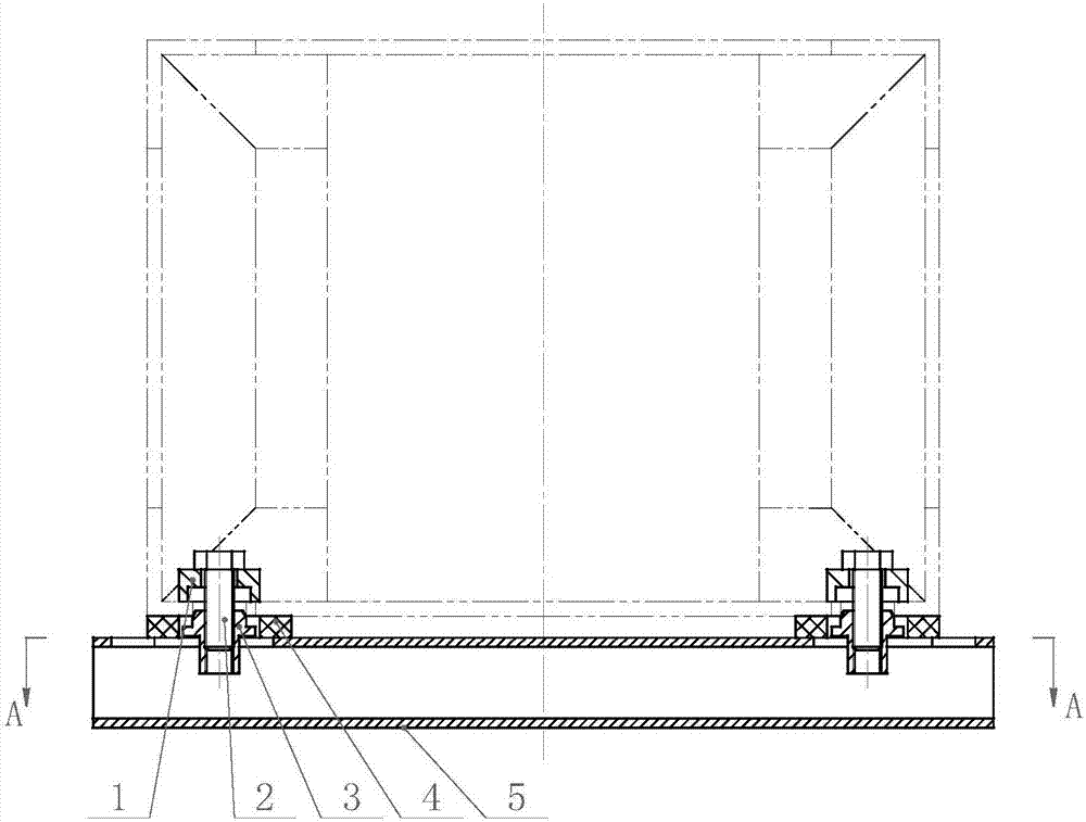
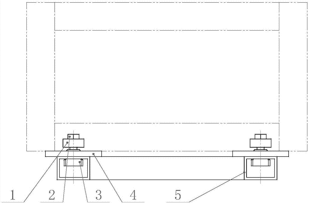
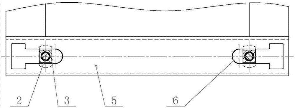
[0027] Such as figure 1 , 2 , 3, 4, 5, and 6, the present invention includes a washer 1, a bolt 2, a locking block 3, a buffer pad 4, a fixing frame 5, and a guide rod 7. Corresponding to the 4 installation holes of the product, two symmetrical T-shaped slots 6 are provided on the front and back of the fixed frame 5, and a locking block 3 is provided in the T-shaped slot. Such as Figure 5 As shown, the locking block 3 includes a circular boss 8 and a waist circular boss 9, and the circular boss 8 and the waist circular boss 9 are connected by a square connecting part 10; the end surface of the circular boss 8 A threaded hole is provided at the center, and the size of the circular boss 8 is slightly smaller than the mounting hole of the product.

[0028] The bolt 1 is screwed into the inner hole of the locking block 3 . The washer 1 is set on the bolt 2 and is loc...


PUM


Abstract

The invention discloses a floating positioning and locking mechanism which comprises bolts, locking blocks, cushions and a fixing frame, wherein T-shaped grooves are formed in the fixing frame and correspond to all mounting holes of a product; the locking blocks are arranged in the T-shaped grooves; the cushions are arranged on the peripheries of the locking blocks on the fixing frame; inner threads are formed in inner holes of the locking blocks; and the bolts are in threaded connection with the inner holes of the locking blocks. The floating positioning and locking mechanism disclosed by the invention has the advantages that the floating positioning function is achieved, the difficulty in hoisting a large-scale box-type product is lowered, the product surface is protected from scratches, the labor cost is reduced, and the hoisting efficiency is improved; through the arrangement of the cushions, the impact force generated from a fall of the product can be buffered by the cushions, and the product protecting function can be achieved; and after the bolts are locked, the cushions can serve elastic washers, thereby protecting the bolts from looseness and improving the bolt connection reliability.

Description

technical field [0001] The invention relates to a floating positioning locking mechanism, which is mainly used in the fixing and transportation of large box-type products. The mechanism can automatically guide the locking block into the installation hole of the product, and securely fix the product with the fixing frame. Background technique [0002] In the prior art, in order to hoist a large box-type product onto the fixed frame and fix it through the four mounting holes at the bottom of the product, the fixed frame usually adopts a fixed screw locking structure or a movable ordinary bolt structure. The former requires four workers to control the falling direction at each mounting hole. Due to the high quality of the product and manufacturing errors in the mounting holes and fixing frames, it is difficult for the spreader and operators to accurately control the product direction, and the falling position of the product is prone to shift, resulting in The installation proce...

Claims


Application Information

Patent Timeline
Patent Type & Authority Applications(China)
IPC IPC(8): B65D61/00B65D85/68
CPCB65D61/00B65D85/68B65D2585/6897
Inventor 周云罡李文平廖敏昱刘平
Owner 江南工业集团有限公司
Learn More