Nail blanking assembly for cooling fin glue nail installation and labeling machine

A labeling machine and nail dropping technology, which is applied to conveyor objects, conveyors, transportation and packaging, etc., can solve the problems of forehearth stuck, the pneumatic control board cannot be reset, and accurate quantitative blanking cannot be realized.

Inactive Publication Date: 2017-10-24
WUHU TAIQING ELECTRONICS TECH CO LTD
View PDF7 Cites 4 Cited by
  • Summary
  • Abstract
  • Description
  • Claims
  • Application Information

AI Technical Summary

Problems solved by technology

The heat sinks processed in the prior art are in the form of flakes, which need to be installed with rubber nails. However, in the existing automatic production equipment, when installing the rubber nails, most of them use slender material channels, and the rubber nails in the material channels are tightly Next to each other, the blanking of rubber nails is controlled pneumatically; in this way, during the production process, when blanking, the pneumatic control panel is opened, and multiple materials will be dropped at one time, which cannot achieve accurate quantitative blanking, and will also cause the material channel to be stuck , the problem that the pneumatic control board cannot be reset, and a series of mechanical failures will follow

Method used


Image

  • Nail blanking assembly for cooling fin glue nail installation and labeling machine
  • Nail blanking assembly for cooling fin glue nail installation and labeling machine
  • Nail blanking assembly for cooling fin glue nail installation and labeling machine

Examples


Embodiment Construction

[0026] Below in conjunction with accompanying drawing and embodiment of description, specific embodiment of the present invention is described in further detail:

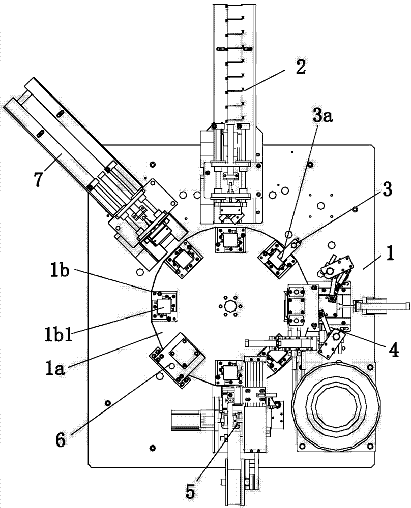
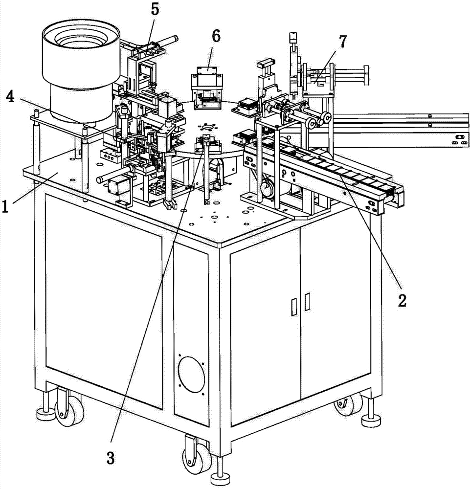
[0027] refer to figure 1 with figure 2 As shown, a labeling machine with rubber nails for heat sinks includes a workbench 1, which is provided with a turntable 1a, and the turntable 1a is pivotally connected to a certain shaft above the workbench 1 through a bearing mechanism. The workbench 1 The stepper motor that drives the turntable 1a to move stepwise around the fixed axis is located below the turntable 1a. The turntable 1a is provided with a number of positioning fixtures 1b that are evenly distributed along the circumference. The direction of rotation is provided with heat sink feeding device 2, heat sink in-position detection device 3, rubber nail installation device 4, heat sink labeling device 5, label pressing device 6 and heat sink unloading device 7.

[0028] The positioning fixture 1b includes an emb...


PUM


Abstract

The invention relates to the field of automation equipment, in particular to a nail blanking assembly for a cooling fin glue nail installation and labeling machine. The nail blanking assembly comprises a supporting frame, an installation block, a second air cylinder, a rotating wheel, an insertion needle, a blanking plate and a nail blanking pipe. The second air cylinder is installed below the top of the supporting frame in an inverted mode. The installation block is fixedly connected with the supporting frame and located below the second air cylinder. The rotating wheel is pivoted to the installation block through a bearing. The second air cylinder is connected with the eccentric position of the back of the rotating wheel. The insertion needle and the blanking plate are in transmission connection with the eccentric position of the front portion of the rotating wheel, the connection position of the insertion needle and the eccentric position of the front portion of the rotating wheel is away from the connection position of the blanking plate and the eccentric position of the front portion of the rotating wheel, and a connection line of the insertion needle and the eccentric position of the front portion of the rotating wheel and a connection line of the blanking plate and the eccentric position of the front portion of the rotating wheel penetrate through the circle center of the rotating wheel. The nail blanking pipe is of a hollow structure. The blanking plate can move at the bottom of the nail blanking pipe through driving of the rotating wheel so that opening and closing of the bottom of the nail blanking pipe can be controlled. The insertion needle can be inserted into the middle section of the nail blanking pipe through driving of the rotating wheel. According to the nail blanking assembly for the cooling fin glue nail installation and labeling machine, the blanking amount can be precisely controlled, the effect that the blanking amount is one each time is ensured, and thus the working efficiency of other mechanisms cannot be affected.

Description

technical field [0001] The invention relates to the field of automation equipment, in particular to a nail-feeding assembly of a heat sink-mounted rubber nail labeling machine. Background technique [0002] Heat sink is a commonly used component, which is used in various fields, especially in the field of electronic equipment, where it is widely used. The heat sinks processed in the prior art are in the form of flakes, which need to be installed with rubber nails. However, in the existing automatic production equipment, when installing the rubber nails, most of them use slender material channels, and the rubber nails in the material channels are tightly Next to each other, the blanking of rubber nails is controlled pneumatically; in this way, during the production process, when blanking, the pneumatic control panel is opened, and multiple materials will be dropped at one time, which cannot achieve accurate quantitative blanking, and will also cause the material channel to be...

Claims


Application Information

Patent Timeline
Patent Type & Authority Applications(China)
IPC IPC(8): B65G47/08
CPCB65G47/08B65G2201/02
Inventor 江远生
Owner WUHU TAIQING ELECTRONICS TECH CO LTD
Why Eureka
Try Eureka