Physical layer secure coding system based on Ethernet communication

A technology of physical layer security and coding system, applied in the field of physical layer security communication, can solve the problems of complex realization, safety distance gap, can not well guarantee the reliability of physical layer coding, etc., to achieve the effect of coordination work and convenient testing

Active Publication Date: 2017-11-10
NO 54 INST OF CHINA ELECTRONICS SCI & TECH GRP
View PDF3 Cites 3 Cited by
  • Summary
  • Abstract
  • Description
  • Claims
  • Application Information

AI Technical Summary

Problems solved by technology

Although the above security coding technology is relatively mature, the implementation is relatively complicated, and there is a gap between the reduced safety distance and the ideal value, which cannot guarantee the reliability of the physical layer coding well.

Method used


Image

  • Physical layer secure coding system based on Ethernet communication
  • Physical layer secure coding system based on Ethernet communication
  • Physical layer secure coding system based on Ethernet communication

Examples


Embodiment 1

[0034] like Figure 1-3 shown.

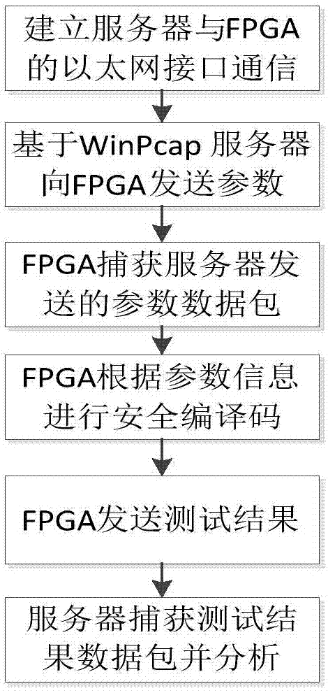
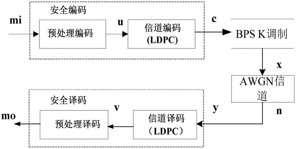
[0035] A physical layer security encoding system based on Ethernet communication includes a server, an FPGA module and an auxiliary Ethernet communication platform; the FPGA module includes a physical layer PHY chip, a MAC controller and a FIFO memory; the FPGA module realizes a secure encoding and decoding function.

Embodiment 2

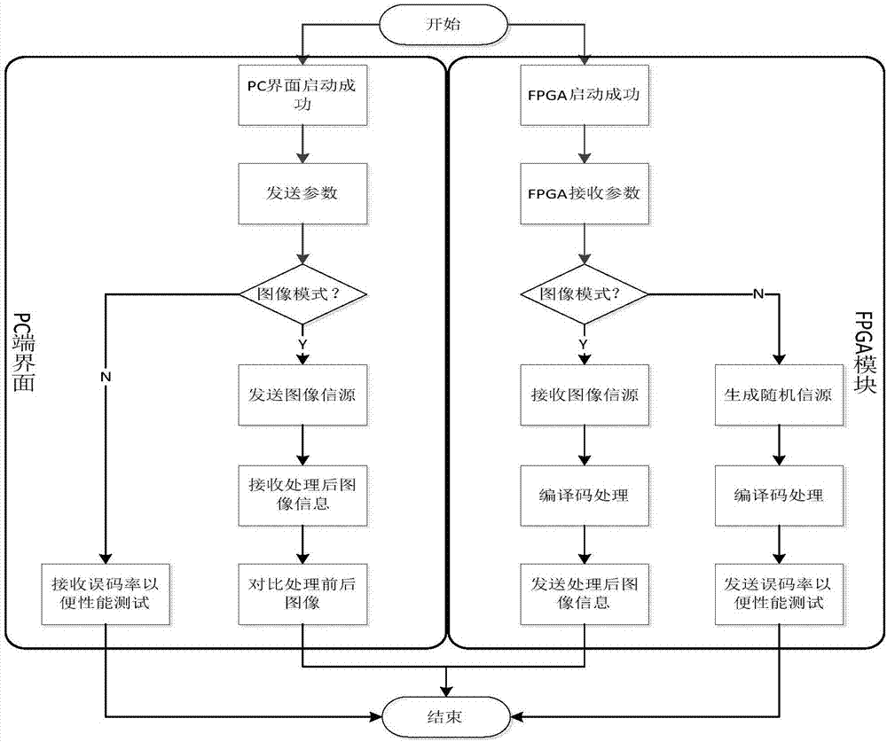
[0037]The physical layer security encoding system based on Ethernet communication as described in embodiment 1, the difference is that the working mode of the server includes image transmission mode and safe distance measurement mode; Send the image source, the FPGA module securely encodes the image source and sends it back to the server, the server compares the image source before and after processing, and judges the security coding performance of the system; in the performance test mode, the FPGA module generates a random source, And send the bit error rate data of the random source under different signal-to-noise ratios to the server, and the server analyzes the bit error rate data to judge the security coding performance of the system. The system can be divided into two modes: performance test and image transmission. In the performance test mode, the server receives the bit error rate sent by the FPGA to realize the performance test of secure coding. In the image transmissi...

Embodiment 3

[0039] The physical layer security encoding system based on Ethernet communication as described in Embodiment 2, the difference is that under the image transmission mode, the server selects the image transmission control parameters, and transmits the image transmission control parameters and image sources to the FPGA module The image transmission control parameters include the code length, code rate and channel SNR of the image source; under the safe distance measurement mode, the server selects random transmission control parameters, and transmits random transmission control parameters to the FPGA module. The random transmission control parameters include the code length and code rate of the random source, and the start point, end point, and interval of the channel SNR.


PUM


Abstract

The invention relates to a physical layer secure coding system based on Ethernet communication. The system includes a server, an FPGA module and an Ethernet communication auxiliary platform. The FPGA module includes a physical layer PHY chip, an MAC controller and an FIFO memory. The FPGA module achieves the function of secure coding and decoding. According to the physical layer secure coding system based on Ethernet communication, communication is realized through the Ethernet communication auxiliary platform. High efficiency, high speed and high performance are obvious advantages of the Ethernet. With the Ethernet as a communication platform, the data transmission rate of the whole system will not affect the work efficiency of the system. Better coordination between hardware and software is realized. The function of physical layer secure coding is completed.

Description

technical field [0001] The invention relates to a physical layer security encoding system based on Ethernet communication, belonging to the technical field of physical layer security communication. Background technique [0002] Efficiency, high speed and high performance are the salient features of Ethernet. According to the OSI seven-layer network model, the key to Ethernet technology lies in the data link layer and the physical layer. The data link layer includes the media access control MAC sublayer and logical chain Road Control LLC sublayer. [0003] Physical layer security coding is a channel coding technology that utilizes the difference of wireless channels to ensure the reliable transmission of information between authorized parties and obtain secure information transmission. It can make private information securely transmitted without using keys. eavesdropped by a third party. In order to better describe the relationship between reliability and safety, the resear...

Claims


Application Information

Patent Timeline
Patent Type & Authority Applications(China)
IPC IPC(8): H04L1/00H04L29/08
CPCH04L1/0009H04L69/323
Inventor 杨勇王涛马丕明
Owner NO 54 INST OF CHINA ELECTRONICS SCI & TECH GRP
Why Eureka
Try Eureka