Automatic mop washing mopping machine

A technology of automatic cleaning and hand mopping, applied in the direction of road cleaning, cleaning methods, cleaning methods and utensils, etc., can solve problems such as trouble, inability to continuously mop the floor, and untimely removal and cleaning, so as to improve the cleaning effect and save water Obvious effect, beneficial to environmental protection

Inactive Publication Date: 2017-10-24
SUINING CHANGFENG MECHANICAL TECH
View PDF0 Cites 11 Cited by
  • Summary
  • Abstract
  • Description
  • Claims
  • Application Information

AI Technical Summary

Problems solved by technology

Although a lot of water was flushed, the flat plate blocked the water on it, and many parts of the mop couldn’t be washed at all, and it couldn’t be washed clean.
The second is that the strip-shaped mop is relatively long, and there is no special dehydration device. After cleaning the strip-shaped mop, the cleaners carry it to mop the floor, causing running water while walking, and people who come and go walk on the ground.
The third is that most of the handkerchiefs are rinsed in the toilet, and it is troublesome, laborious and time-consuming to wash the handkerchiefs once. The cleaners often finish mopping a unit or several floors before washing it once, resulting in the floor after mopping. unclean
Although the speed is fast and the scrubbing width of the mop is wide, this kind of mop cannot be cleaned automatically. You have to remove the mop after mopping a certain area, install it after cleaning, and then work.
In this method, due to the trouble of cleaning, when the mopping handkerchief is already very dirty, the user often does not take it off for cleaning in time, causing the floor to be very dirty section by section, which is the same as the floor that has not been mopped.
Still can't mop the floor continuously

Method used


Image

  • Automatic mop washing mopping machine
  • Automatic mop washing mopping machine
  • Automatic mop washing mopping machine

Examples


Embodiment Construction

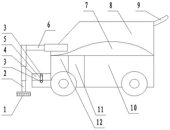
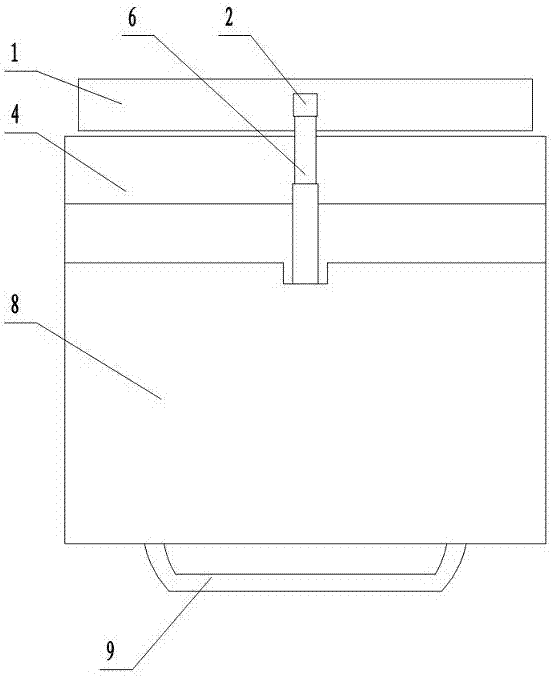
[0012] figure 1 In, is a side view of an automatic cleaning mopping machine. figure 2 in, yes figure 1 top view. combine figure 1 , figure 2 Narrate together. Car body 8 front upper part is equipped with boom 6. The front end of the boom 6 is vertically connected with the upper end of the lifting rod 2 . The lower end of the lifting rod 2 is connected in the middle of the flat plate above the handkerchief 1. figure 1 The mopping seen in is the width direction of the two ends of the mopping. Both the boom and the lifting rod are square telescopic tubes. Hydraulic cylinders are installed in the pipe frame of the jib frame and the lifting rod. The lifting rod can be stretched up and down, driving the mop to move up and down. The boom can be stretched back and forth, driving the handle to move back and forth. Clear water tank 7, secondary sewage tank 12, light sewage tank 11 and sewage tank 10 are arranged in the car body. Cleaning pool 4 is installed in car body 8 f...


PUM


Abstract

The invention provides an automatic mop washing mopping machine. The automatic cleaning mop mopping machine comprises a lifting rod, a mop, an arm frame, a washing pond, a vehicle body, a water feeding and draining part and a control system. The lower end of the lifting handle is connected with one mop, and the upper end of the lifting handle is connected with the front end of the arm frame. The rear end of the arm frame is connected to the vehicle body. The washing pond is arranged in front of the vehicle body, and a stirring and washing device is installed in the washing pond. The vehicle body is provided with a sewage tank, a secondary sewage tank, a light sewage tank and a clear water tank. When the mop is washed, the mopping machine stops movement, the lifting rod is matched with the arm frame, and the mop is lifted to be moved to the middle of the washing pond, and is put into the washing pond. Water in the secondary sewage tank, the light sewage tank and the clear water tank are utilized to conduct stirring and washing in sequence, and dehydration is conducted. Sewage in the previous two times is drained into the sewage tank, and the water obtained in the last two times washed with clear water is drained in the secondary sewage tank and the light sewage tank. After being washed and dehydrated, the mop is transferred to the original position, the mopping machine moves to continue mopping. A large amount of washing water is saved, so that the mopped floor is cleaner, and the work efficiency is improved. The situation that a machine-mounted long-strip shaped mop cannot be automatically washed is changed.

Description

technical field [0001] The invention belongs to the field of environmental protection machinery, in particular to an automatic cleaning mopping machine. Background technique [0002] Now most of the environmental cleaning workers in residential areas, shopping malls, entertainment and leisure places, restaurants, hotels, and office areas use long strips of handkerchiefs to mop the floor. The strip-shaped mopping handkerchief is longer and the mopping area is wider at one time. But the cleaning of strip-shaped mop has always been a very troublesome thing. One is that there is no such long elongated water basin and pond as an elongated mopping handkerchief. Most of them are showered with water and rinsed with tap water. Although a lot of water was flushed, the flat plate blocked the water, and many parts of the mop couldn't be washed at all, and it couldn't be washed clean. The second is that the strip-shaped mop is relatively long, and there is no special dehydration devi...

Claims


Application Information

Patent Timeline
Patent Type & Authority Applications(China)
IPC IPC(8): E01H1/02B08B3/10
CPCB08B3/102E01H1/02
Inventor 邹家福胡冬梅屈胜英
Owner SUINING CHANGFENG MECHANICAL TECH
Why Eureka
Try Eureka