Anti-backflow drainage system
A drainage system and anti-backflow technology, which is applied to the waterway system, sewer system, sewage discharge, etc., can solve the problems of easy backflow in the drainage system, and achieve the effect of simple structure, easy maintenance, and continuous and uniform drainage
- Summary
- Abstract
- Description
- Claims
- Application Information
AI Technical Summary
Problems solved by technology
Method used
Image
Examples
Embodiment 1
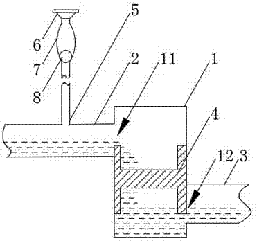
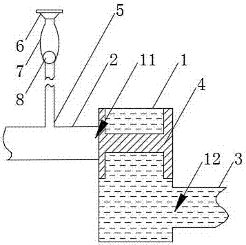
[0031] combined with figure 1 As shown, a kind of anti-backflow drainage system includes drainage branch pipe 5, water collection pipe 2 and discharge pipe 3 connected in sequence, and a rectangular anti-backflow box 1 is arranged between the water collection pipe 2 and discharge pipe 3. The top of the anti-backfill box 1 is provided with a water inlet 11 connected to the water collection pipe 2, and the bottom part is provided with a water outlet 12 connected to the discharge pipe 3. The anti-backfill box 1 is provided with a size larger than the water inlet 11 and cannot The floating block 4 passing through the water outlet 12.
[0032] Implementation principle:
[0033] The density of the floating block 4 is less than that of water, and it is in a floating state in the water.
[0034] Under normal drainage conditions, the water is collected into the water collection pipe 2 through the drainage branch pipe 5, and then flows through the anti-backflow tank 1 and the discharg...
Embodiment 2
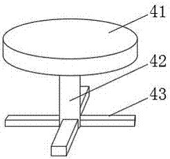
[0038] On the basis of Example 1, in conjunction with the attached image 3 As shown, the water inlet 11 and the water outlet 12 are arranged on the opposite side elevation of the anti-pouring tank 1, and the water stop block 41 included in the floating block 4 is fixed on the water stop block 41 The connecting column 42 and the hollow plate 43 fixed at the end of the connecting column 42 , the connecting column 42 is perpendicular to the hollow plate 43 , and the size of the hollow plate 43 is larger than the water outlet 12 .
[0039] Implementation principle:
[0040] It is worth noting that the shape and structure of the hollow plate 43 are not limited, as long as it cannot pass through and will not block the water outlet 12; 1 on the same side elevation, that is, on the adjacent or opposite side elevation, the water stop block 41 faces the water inlet 11, the hollow plate 43 faces the water outlet 12, and the connecting column 42 can be L-shaped or linear. In this embo...
Embodiment 3
[0044] On the basis of Embodiment 2, further, the overall maximum length and width of the water stop block 41 , the connecting column 42 and the hollow plate 43 are adapted to the length and width of the anti-backflow box 1 .
[0045] Implementation principle:
[0046] The overall maximum length and width of the water stop block 41, the connecting column 42 and the hollow plate 43 are adapted to the length and width of the anti-inverting box 1, that is, the length and width of the floating block 4 and the anti-inverting box 1 Correspondingly, the floating block 4 cannot move arbitrarily in the anti-inverting box 1, but can only move up and down in the height direction of the anti-inverting box 1 with the water level, and the water-stopping block 41 is always attached to the inflowing box 1. On the side elevation where the water inlet 11 is located, when the sewage flows back, the water stop block 41 can rise straight up to block the water inlet 11, so that the speed of prevent...
PUM
 Abstract
Description
Claims
Application Information
 - R&D
- Intellectual Property
- Life Sciences
- Materials
- Tech Scout
- Unparalleled Data Quality
- Higher Quality Content
- 60% Fewer Hallucinations
Browse by: Latest US Patents, China's latest patents, Technical Efficacy Thesaurus, Application Domain, Technology Topic, Popular Technical Reports.
© 2025 PatSnap. All rights reserved.Legal|Privacy policy|Modern Slavery Act Transparency Statement|Sitemap|About US| Contact US: help@patsnap.com


