An application of ct to measure co in porous media 2 - Method of change in brine interface area

A technology of interface area and porous media, applied in the direction of measuring devices, using wave/particle radiation, material analysis using wave/particle radiation, etc., can solve the failure to consider the change of flow field interface, the influence of interface change, etc. question

Active Publication Date: 2019-11-08
DALIAN UNIV OF TECH
View PDF5 Cites 0 Cited by
  • Summary
  • Abstract
  • Description
  • Claims
  • Application Information

AI Technical Summary

Problems solved by technology

Most of the measurement process is to pre-mix the non-aqueous liquid, water and porous media, or to set the residual saturation state of the non-aqueous liquid phase in water by continuously injecting the non-aqueous liquid and water into the porous media. Considering the influence of mass transfer between two phases on interface changes in the real environment
And most of them use a single injection direction, failing to consider the interface changes caused by the flow field being affected by gravity
[0005] Considering CO 2 - The characteristics of brine in the actual formation environment, and its mass transfer process will be affected by factors such as heterogeneity, temperature and pressure, flow rate and gravity. 2 - There are certain deficiencies in the determination of the interfacial area change during the brine mass transfer process

Method used


Image

  • An application of ct to measure co in porous media  <sub>2</sub> - Method of change in brine interface area
  • An application of ct to measure co in porous media  <sub>2</sub> - Method of change in brine interface area
  • An application of ct to measure co in porous media  <sub>2</sub> - Method of change in brine interface area

Examples


Embodiment Construction

[0042] The specific embodiments of the present invention will be described in detail below in conjunction with the technical solutions and accompanying drawings.

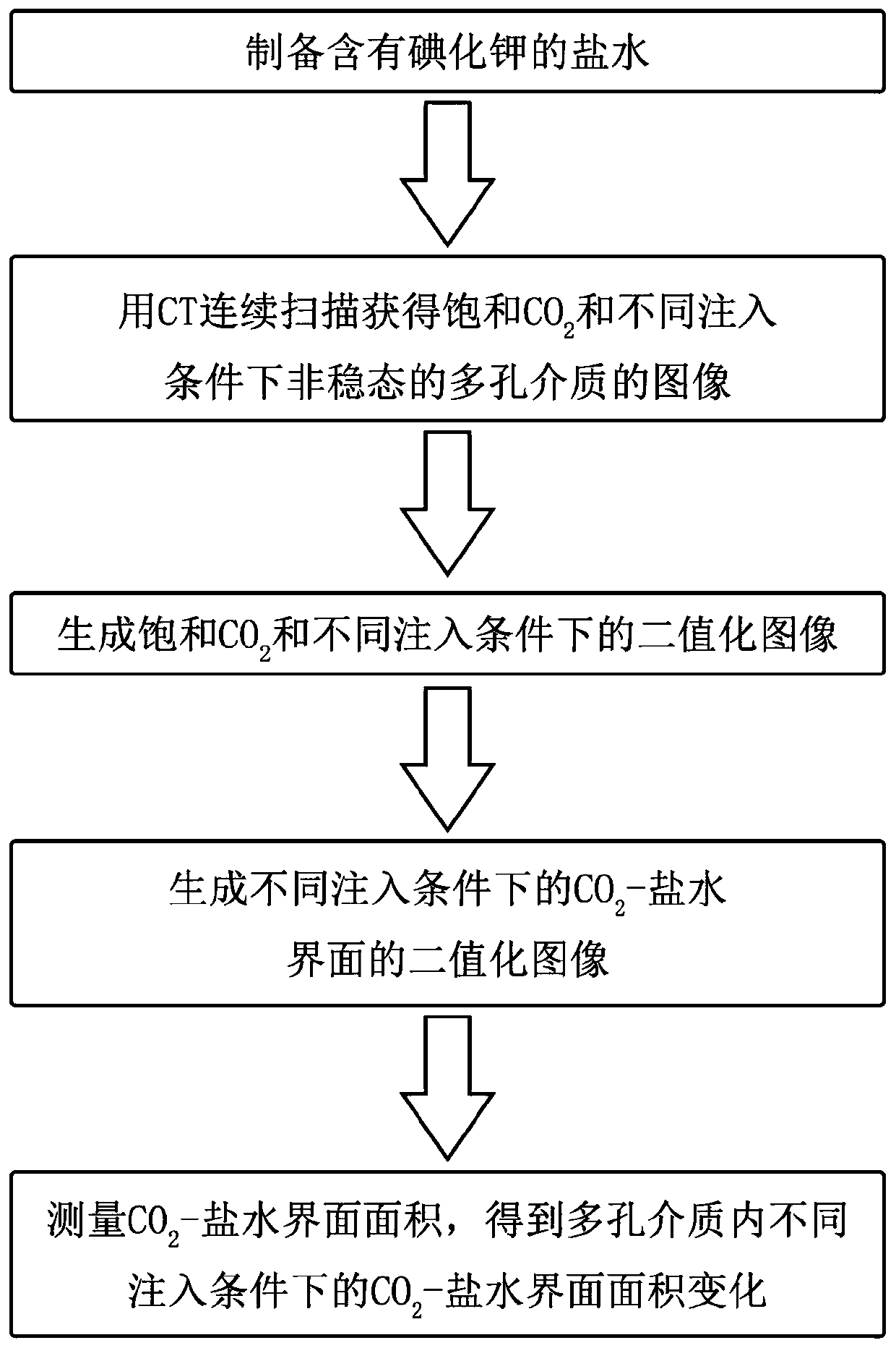
[0043] The example is under the conditions of 40°C and 8MPa, using CT to measure the CO in porous media under different injection conditions. 2 - Brine interface area change.

[0044] The first step prepares brine containing potassium iodide;

[0045] Add 9 g of potassium iodide to 100 ml of brine to make the density of the brine solution approximately equal to 83.7% of the density of the porous medium to enhance the CO 2 - image contrast of saline;

[0046] In the second step, continuous scanning with CT to obtain saturated CO 2 and images of unsteady porous media under different injection conditions;

[0047] Set the temperature and pressure at 40°C and 8MPa; before injecting brine, fill the porous medium with CO 2 The high-pressure container is connected to the experimental system, and the saturated CO is ob...


PUM


Abstract

The invention relates to a method for measuring area changes of CO2-saline water interfaces in a porous medium by using a CT. The method comprises the steps of firstly preparing saline water containing potassium iodide to strengthen the image contrast of CO2-saline water; continuously scanning by using the CT to obtain unsteady-state porous medium images under the CO2-saturated condition and different injection conditions; removing a noisy point by using a filter and carrying out threshold processing to generate binary images only containing 0 and 1 of saturated CO2 and under different injection conditions; carrying out subtraction on two image stacks to obtain distribution areas of the saline water in the binary images; extracting the edges of the distribution areas of the CO2 and the saline water and determining a union set to generate binary image slice stacks of the CO2-saline water interfaces; obtaining the area changes of the CO2-saline water interface in the porous medium under different injection conditions through determining and measuring the area of disconnected CO2-saline water interfaces; and calculating the saturability of the saline water in each image slice stack and obtaining area change characteristic parameters of the CO2-saline water interfaces under different injection conditions through induction.

Description

technical field [0001] The invention belongs to the technical field of multiphase fluid flow measurement in porous media, and relates to a method for measuring CO in porous media using CT. 2 - Method of change in brine interface area. Background technique [0002] Carbon dioxide brine storage technology converts millions of tons of CO 2 Injected into the brine layer, resulting in a complex multiphase fluid migration process. In formation environments, mobile CO 2 The plume produces numerous clusters of cord-like air bubbles behind and around it. With being CO 2 The brine around the occupied pores gradually infiltrated into the pores, and the CO 2 Bubble clusters will slowly dissolve in the invading brine, and the time scale of this process is related to the mass transfer rate between the two phases. When CO 2 with unsaturated CO 2 When the brine is in contact, the mass transfer between the two phases mainly occurs in the CO 2 - at the brine interface. CO 2 gradual...

Claims


Application Information

Patent Timeline
Patent Type & Authority Patents(China)
IPC IPC(8): G01N23/046G01B15/00
CPCG01B15/00G01N23/046G01N2223/1016
Inventor 宋永臣蒋兰兰武博浩刘瑜杨明军张毅赵越超吕鹏飞王大勇
Owner DALIAN UNIV OF TECH
Why Eureka
Try Eureka