Supercharge Your Innovation With Domain-Expert AI Agents!

Chromatographic column temperature control circuit

A temperature control and chromatographic column technology, applied in temperature control, non-electric variable control, control/regulation system, etc., can solve the problems of slow heating speed, discontinuous voltage, uneven column temperature, etc. temperature, reduce heating power consumption, and reduce the effect of analysis time

Active Publication Date: 2017-10-24
INST OF ACOUSTICS CHINESE ACAD OF SCI
View PDF11 Cites 5 Cited by
  • Summary
  • Abstract
  • Description
  • Claims
  • Application Information

AI Technical Summary

Problems solved by technology

Affects the performance of the gas chromatograph
It is reflected in unstable retention time, messy chromatogram, and deformed peaks
Secondly, the temperature rise rate of the above devices is relatively slow, which is not suitable for rapid analysis and trace detection
Third, the pulse heating method will cause the voltage applied across the column to be discontinuous, resulting in uneven column temperature
Fourth, the device is assembled from multiple instruments without system integration and automatic control, and is not suitable for portable instruments

Method used


Image

  • Chromatographic column temperature control circuit
  • Chromatographic column temperature control circuit
  • Chromatographic column temperature control circuit

Examples


Embodiment Construction

[0026] In order to make the object, technical solution and advantages of the present invention clearer, the present invention will be further described in detail below in conjunction with the accompanying drawings. Obviously, the described embodiments are only some embodiments of the present invention, rather than all embodiments . Based on the embodiments of the present invention, all other embodiments obtained by persons of ordinary skill in the art without making creative efforts belong to the protection scope of the present invention.

[0027] The technical method of the present invention will be described in further detail below with reference to the accompanying drawings and embodiments.

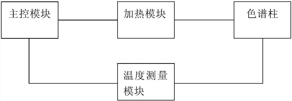
[0028] figure 2 The schematic diagram of the chromatographic column temperature control circuit provided by the embodiment of the present invention. like figure 2 As shown, this embodiment includes:

[0029] Chromatographic column 11, heating module 12, temperature measurement mo...


PUM


Abstract

The invention relates to a chromatographic column temperature control circuit which comprises a heating module for heating a chromatographic column, a temperature measurement module for measuring the current temperature of the chromatographic column, and a main control module for obtaining the current temperature of the chromatographic column from the temperature measurement module, wherein when the current temperature is first temperature, low-temperature constant-temperature regulation is performed; when the current temperature is second temperature, high-temperature constant-temperature regulation is performed; and when the current temperature is between the first temperature and the second temperature, programmed temperature rise regulation is performed. According to the chromatographic column temperature control circuit, continuous voltage heating is applied to the chromatographic column, so that rapid linear temperature rise and low and high-temperature control are realized, the analysis time is shortened, the heating power consumption is reduced, and on-site analysis and detection of a gas chromatograph are realized.

Description

technical field [0001] The invention relates to the field of electronic circuits, in particular to a chromatographic column temperature control circuit. Background technique [0002] Gas chromatography is a common type of chromatography used to separate and analyze compounds that can evaporate without decomposing, and is used in analytical chemistry to analyze mixtures. During use, the carrier gas pushes the vaporized sample in the inlet into the chromatographic column, and the temperature of the chromatographic column is programmed to increase the resolution of the sample, and reduce the noise in the chromatogram. [0003] According to the length of the chromatographic column, the temperature control method of the chromatographic column can be divided into direct heating and indirect heating. For example, the chromatographic column heating method invented in Patent Application No. 201310754095.1 is to heat the aluminum ingot, and then use a fan to transfer the heat to the ...

Claims


Application Information

Patent Timeline
IPC IPC(8): G01N30/54G05D23/22
CPCG01N30/54G01N2030/025G05D23/22
Inventor 刘明华孔银鸽何世堂李顺洲刘鑫璐郝俊杰
Owner INST OF ACOUSTICS CHINESE ACAD OF SCI
Features
  • R&D
  • Intellectual Property
  • Life Sciences
  • Materials
  • Tech Scout
  • Unparalleled Data Quality
  • Higher Quality Content
  • 60% Fewer Hallucinations
Learn More