Constant current starting circuit applied to boost converter

A boost converter and start-up circuit technology, applied in the electronic field, can solve problems such as large surge current, abnormal operation of the circuit system, damage to the switch tube, etc., and achieve the effect of eliminating the surge current

Active Publication Date: 2017-10-24
UNIV OF ELECTRONICS SCI & TECH OF CHINA +1
View PDF3 Cites 6 Cited by
  • Summary
  • Abstract
  • Description
  • Claims
  • Application Information

AI Technical Summary

Problems solved by technology

[0006] When starting, if the output voltage is too low, the input and output pressure difference will be large, and the rising slope of the inductor current will be very large, which will cause a large surge current during starting, which may damage the switch tube M P , energy storage inductor L or other devices, resulting in abnormal operation of the circuit system
In addition, in practical applications, the Boost converter is usually directly connected to the battery of a portable electronic device. Due to the internal resistance and heat generation of the battery, the instantaneous surge current may cause the battery to burn out.

Method used


Image

  • Constant current starting circuit applied to boost converter
  • Constant current starting circuit applied to boost converter
  • Constant current starting circuit applied to boost converter

Examples


Embodiment Construction

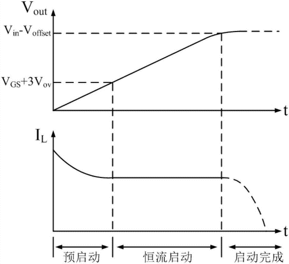
[0025]In order to eliminate the surge current in the start-up phase, the present invention adopts the method of clamping the charging current to a fixed value, and uses a current mirror and a constant bias current to limit the charging current to a fixed value in the soft-start phase, thereby realizing a constant value in the soft-start phase. stream charging. The specific implementation manner and principle of the present invention will be further elaborated below in conjunction with the drawings.

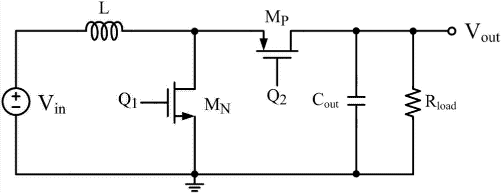
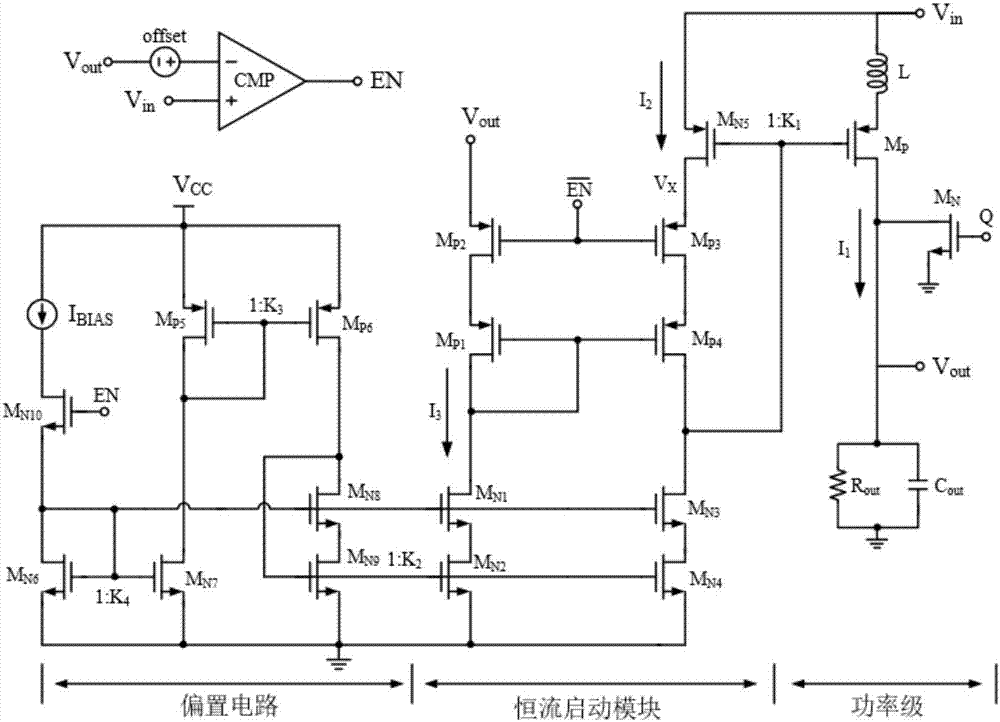
[0026] Such as figure 2 Shown is a circuit implementation structure of the boost converter constant current starting circuit proposed by the present invention, including a power stage, a constant current starting module, a bias circuit module and an enabling module. The bias circuit module generates a constant first bias The setting current and the second bias current provide accurate constant current for the constant current starting module, and the enabling module generates th...


PUM


Abstract

The invention discloses a constant current starting circuit applied to a boost converter, and belongs to the technical field of the electronic. The constant current starting circuit comprises a power level, a constant current starting module, a bias circuit module and an enabling module, wherein the bias circuit module is used for producing the constant first bias current and second bias current to provide for the constant current starting module; the enabling module is used for producing an enabling signal EN to control the on and off of the bias circuit module and the constant current starting module; the constant current starting module is used for limiting the power-level charging current as a fixed value by using a current mirror and the constant bias current. By clamping the charging current, namely the inductive current as the fixed value, the constant current charging at the soft starting stage is realized, and the surge current at the circuit starting stage of the boost converter is eliminated.

Description

technical field [0001] The invention belongs to the field of electronic technology, and in particular relates to the design of a constant current starting circuit applied to a Boost (boost converter) converter. Background technique [0002] Boost converters are widely used in electronic computers, various electronic terminal equipment, and communication equipment due to their small size, light weight and high efficiency. [0003] A typical Boost converter architecture such as figure 1 As shown, mainly by the switching power tube M N , M P , energy storage inductor L, output capacitor C out , load R load composition. The basic working principle is: using the energy storage characteristics of inductance and capacitance, in the switch tube M N Conduction, M P When turned off, the current passes through the inductor and is converted into magnetic energy and stored in the inductor; M N off, M P When turned on, the inductor passes through M P Discharge, transfer the stor...

Claims


Application Information

Patent Timeline
Patent Type & Authority Applications(China)
IPC IPC(8): H02M1/36H02M1/32H02M3/158
CPCH02M1/32H02M1/36H02M3/1582
Inventor 明鑫唐韵扬程政高笛魏秀凌王卓张波
Owner UNIV OF ELECTRONICS SCI & TECH OF CHINA
Why Eureka
Try Eureka