Direction-adjustable auto-clamping perforating machine for electronic devices

An electronic device and automatic clamping technology, which is applied in the field of electronic information, can solve the problems of wasting time, prone to accidental injuries, and increasing the labor force of employees, and achieve the effects of slowing down collisions, improving implementability, and improving operation rationality

Inactive Publication Date: 2017-10-27
石国华
View PDF0 Cites 3 Cited by
  • Summary
  • Abstract
  • Description
  • Claims
  • Application Information

AI Technical Summary

Problems solved by technology

[0003] The purpose of the present invention is to provide an automatic clamping and punching machine for electronic devices with adjustable orientation, which has the advantages of freely changing the processing and punching orientation and automatic clamping, and solves the problem of the existing electronic devices that need to be punched in different directions. Stopping and changing directions not only wastes time but also increases the labor force of employees, and repeated manual clamping is required to change the punching position repeatedly. Multiple manual clampings are not only prone to accidental injuries

Method used


Image

  • Direction-adjustable auto-clamping perforating machine for electronic devices
  • Direction-adjustable auto-clamping perforating machine for electronic devices
  • Direction-adjustable auto-clamping perforating machine for electronic devices

Examples


Embodiment Construction

[0025] The following will clearly and completely describe the technical solutions in the embodiments of the present invention with reference to the accompanying drawings in the embodiments of the present invention. Obviously, the described embodiments are only some of the embodiments of the present invention, not all of them. Based on the embodiments of the present invention, all other embodiments obtained by persons of ordinary skill in the art without making creative efforts belong to the protection scope of the present invention.

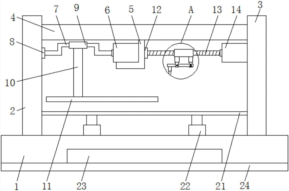
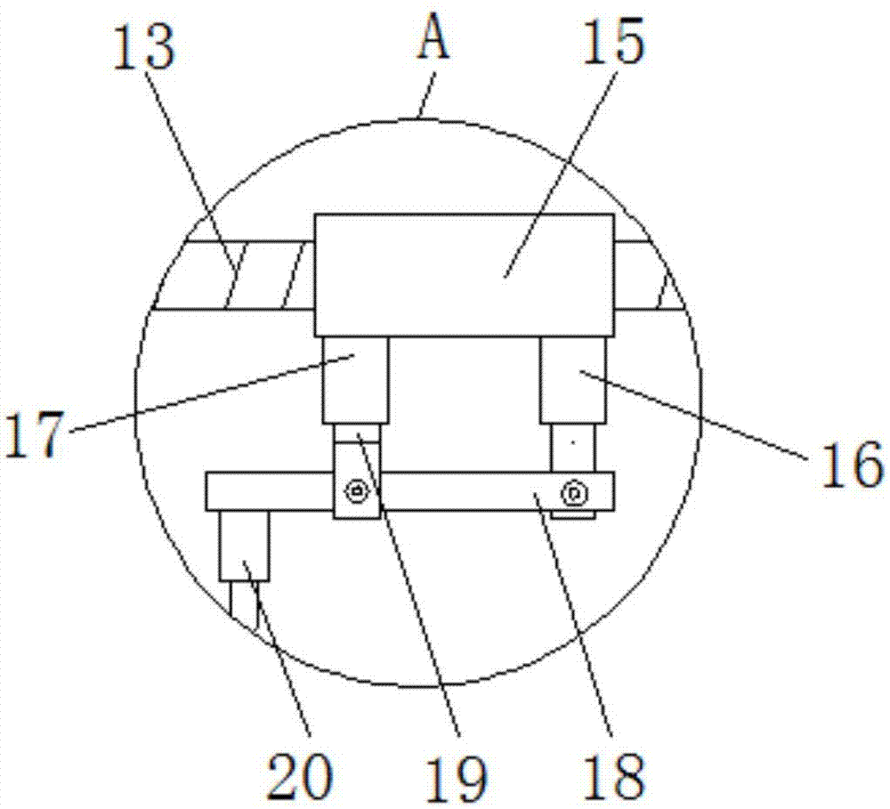
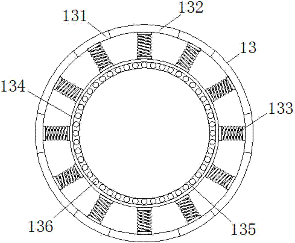
[0026] see Figure 1-4, an automatic clamping puncher for electronic devices with adjustable orientation, comprising a base (1), the bottom of the base (1) is inlaid with a weight-increasing plate (23), and the bottom of the weight-increasing plate (23) is connected to the base (1 ) are located on the same horizontal plane, which increases the weight of the overall bottom, lowers the overall center of gravity, avoids tilting due to accidental col...


PUM


Abstract

The invention discloses an automatic clamping and punching machine for electronic devices with adjustable orientation, which comprises a base, and the top of the base is fixedly connected with a symmetrical first support rod and a second support rod, the first support rod and the second support rod A cross bar is arranged between them, the bottom of the cross bar is fixedly connected with a folded plate, the inner wall of the folded plate is fixedly connected with a first motor, the output end of the first motor is fixedly connected with a folded rod, and the end of the folded rod far away from the first motor is provided with a The first bearing, the outside of the first bearing is fixedly connected to the outer surface of the first support rod, the inner wall of the first bearing is fixedly connected to the outer surface of the folding rod, and the outer surface of the folding rod is provided with a second bearing, the second bearing The inner wall of the second bearing is fixedly connected with the outer surface of the folding rod, and the outer surface of the second bearing is fixedly connected with a movable rod. The present invention enables the whole to realize multi-directional drilling, and enables the whole to realize automatic clamping, reduces the participation of workers, and reduces the occurrence of accidental injuries.

Description

technical field [0001] The invention relates to the technical field of electronic information, in particular to an automatic clamping and punching machine for electronic devices with adjustable orientation. Background technique [0002] Electronic information is a term that has appeared frequently in recent years. It has become a vocabulary of informatics under the background of the rapid development of computer technology, communication technology and high-density storage technology and its wide application in various fields. In terms of storage, dissemination and application, it has fundamentally broken the long-term dominance of information storage and dissemination by paper carriers, and represents the development direction of the information industry. With the development of electronic information, electronic information products are increasing day by day, and electronic devices It is a common electronic information product. During the processing of electronic devices, ...

Claims


Application Information

Patent Timeline
Patent Type & Authority Applications(China)
IPC IPC(8): B26F1/24B26D7/02B26D7/26B26D7/00
CPCB26F1/24B26D7/00B26D7/025B26D7/2628B26D2007/0012
Inventor 石国华
Owner 石国华
Why Eureka
Try Eureka