Roller water-entering/returning pipeline system device for two-roll calender

A technology of return water pipes and system devices, which is applied in the field of calender roller machinery, can solve the problems of affecting the speed of water flow, affecting the production time of equipment, and the failure of production of covered sticky rollers, so as to reduce the downtime of equipment cleaning and reduce the The number of equipment failures and the effect of flexible ideas

Pending Publication Date: 2017-10-27
DOUBLE COIN GRP JIANGSU TIRE
View PDF4 Cites 5 Cited by
  • Summary
  • Abstract
  • Description
  • Claims
  • Application Information

AI Technical Summary

Problems solved by technology

[0002] At present, the surface temperature of the rollers in the two-roller calendering memory is overheated, which leads to the failure of the production of the skin-coated sticky rollers. After this phenomenon occurs, it is necessary to arrange an outsourced unit to clean the two rollers, resulting in a long downtime, which affects the normal production time of the equipment. At the same time The maintenance cost also affects the economy. In the past, the water flow direction of the cooling pipe inside the roller was from front to back, passing through the water collecting chamber and then flowing out from the return pipe, which would cause the cooled water to stay in the water collecting chamber and affect the water flow rate. , and the water inlet pipe in the front will hinder the water outlet of the return pipe, the water flow speed will be affected, and the cooling effect will be poor

Method used


Image

  • Roller water-entering/returning pipeline system device for two-roll calender
  • Roller water-entering/returning pipeline system device for two-roll calender
  • Roller water-entering/returning pipeline system device for two-roll calender

Examples


Embodiment Construction

[0012] specific implementation plan

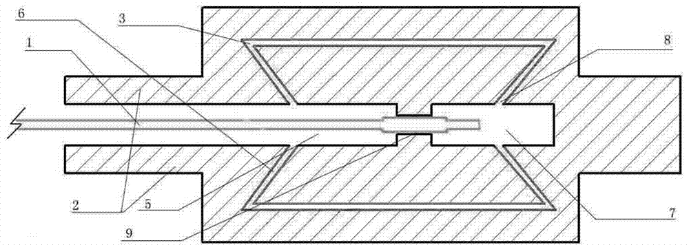
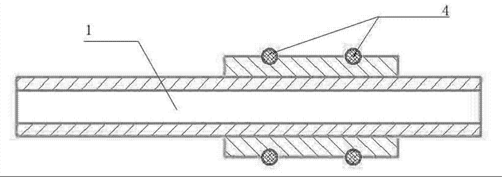
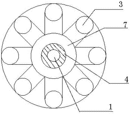
[0013] refer to Figure 1-3 , a two-roll calender roller inlet and return pipeline system device, which includes roller 2, return water channel 5, intermediate transition channel 9, distribution pipeline 7, water inlet pipe 1, cooling flow channel 3, and the inside of the roller is designed with The water inlet and return pipes are divided into the return water channel 5, the intermediate transition channel 9, and the distribution pipe 7. The cooling flow channel 3 is arranged inside the roller 2 close to the outer wall of the roller 2. The water inlet branch of the cooling flow channel 3 The channel 8 and the outlet branch channel 6 are respectively connected to the distribution pipe 7 and the return channel 5, and the return channel 5 is formed between the water inlet pipe 1 and the inner wall of the roller 2, and the water inlet pipe 1 passes through the return channel 5 and passes through the intermediate transition channel 9, Extendi...


PUM


Abstract

The invention relates to a roller water-entering / returning pipeline system device for a two-roll calender. The device comprises a roller, a water returning channel, a middle transition channel, a distribution pipeline, a water entering pipe and a cooling channel, wherein the water-entering / returning pipeline is designed in the roller; the water-entering / returning pipeline is divided into the water returning channel, the middle transition channel and the distribution pipeline; the cooling channel is arranged in the roller close to the outer wall of the roller; a water entering branch and a water draining branch of the cooling channel are respectively connected with the distribution pipeline and the water returning channel; the water returning channel is formed between the water entering pipe and the inner wall of the roller; and the water entering pipe passes by the water returning channel, penetrates through the middle transition channel, extends into the distribution pipeline and is in sealing connection with a matching joint of the water entering pipe in the middle transition channel and the inner wall of the roller. The roller water-entering / returning pipeline system device has the advantages of simple and convenient design, flexible conception, high sealing property, high water pressure in the roller and capabilities of increasing the circulating speed of water in the cooling channel, promoting the cooling effect, reducing the cleaning and halting time of the device and the fault times of the device and reducing the labor intensity of the operator.

Description

technical field [0001] The invention relates to the mechanical field of calender rollers, in particular to a two-roller calender roller water inlet and return pipeline system device. technical background [0002] At present, the surface temperature of the rollers in the two-roller calendering memory is overheated, which leads to the failure of the production of the skin-coated sticky rollers. After this phenomenon occurs, it is necessary to arrange an outsourced unit to clean the two rollers, resulting in a long downtime, which affects the normal production time of the equipment. At the same time The maintenance cost also affects the economy. In the past, the water flow direction of the cooling pipe inside the roller was from front to back, passing through the water collecting chamber and then flowing out from the return pipe, which would cause the cooled water to stay in the water collecting chamber and affect the water flow rate. , and the water inlet pipe in the front wil...

Claims


Application Information

Patent Timeline
Patent Type & Authority Applications(China)
IPC IPC(8): B29C43/24B29C43/46B29C43/52
CPCB29C43/24B29C43/46B29C43/52
Inventor 樊学峰胡亮亮杨鸣锋
Owner DOUBLE COIN GRP JIANGSU TIRE
Why Eureka
Try Eureka