Check valve assembly, gas-lift valve, gas-lift tool and integrated string
A single-flow valve and gas lift valve technology, which can be used in the production of fluids, drill pipes, casings, etc., can solve problems such as low work efficiency and waste of resources.
- Summary
- Abstract
- Description
- Claims
- Application Information
AI Technical Summary
Problems solved by technology
Method used
Image
Examples
Embodiment 1
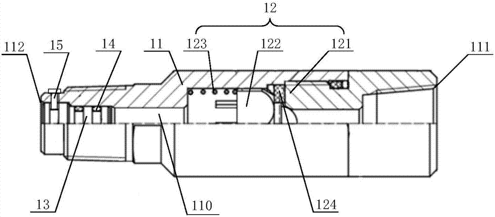
[0030] figure 1 A schematic structural diagram of a one-way valve assembly provided in Embodiment 1 of the present invention, as shown in figure 1 As shown, the one-way valve assembly 1 provided in this embodiment includes: a valve body 11, a one-way assembly 12 and a plug 13;
[0031] Wherein, a through hole 110 is provided inside the valve body 11, the first end 111 of the through hole is connected to the bellows 2, and the second end 112 of the through hole is provided with a plug 13, when the pressure at the second end 112 of the through hole reaches the first pressure , the plug 13 is separated from the second end 112 of the through hole.
[0032] The one-way component 12 is arranged in the through hole 110. When the fluid flowing through the valve body 11 flows from the first end 111 of the through hole to the second end 112 of the through hole, the one-way component 12 is opened, so that the through hole 110 is in a smooth state; When the fluid flows from the second e...
Embodiment 2
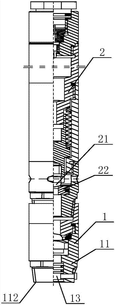
[0046] figure 2 A schematic structural view of the gas lift valve provided in Embodiment 2 of the present invention, as shown in figure 2 As shown, this embodiment provides a gas lift valve, which includes the check valve assembly 1 provided in the first embodiment above, and the bellows 2 .
[0047] Specifically, the bellows 2 is provided with a valve ball 21 and a valve seat 22, and the end of the bellows 2 is connected to the check valve assembly 1, that is, the end of the bellows 2 is connected to the inside of the valve body 11 of the check valve assembly 1. The first end 111 of the through hole is fixedly connected.
[0048] Wherein, the structure and working principle of the check valve assembly 1 are the same as those of the above-mentioned embodiments, and will not be repeated here. The bellows 2 is pre-filled with high-pressure nitrogen to provide closing pressure for the gas lift valve. When the annular pressure exceeds the closing pressure, the bellows 2 is com...
Embodiment 3
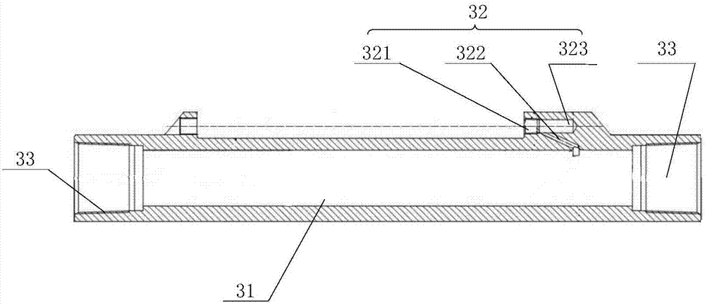
[0052] image 3 Schematic diagram of the structure of the gas lift mandrel provided in Embodiment 3 of the present invention, as shown in image 3 As shown, the gas lift tool 3 provided in this embodiment includes the gas lift valve provided in Embodiment 2 and the gas lift mandrel.
[0053] Specifically, the gas lift working cylinder includes: a hollow cylinder body 31 and a fixed chamber 32 arranged on the outer wall of the cylinder body 31 and close to the end of the cylinder body 31 .
[0054] Preferably, both ends of the cylinder body 31 are provided with threaded connection holes 33, and the two ends of the cylinder body 31 are connected to the oil pipe through the threaded connection holes 33, and the threaded connection holes 33 are air-tight buckles.
[0055] Optionally, the threaded connecting hole 33 can be an internally threaded connecting hole and be air-tight. Specifically, the air-tight seal is sealed by a metal end face. After being put in place, the end face...
PUM
 Abstract
Description
Claims
Application Information
 - R&D
- Intellectual Property
- Life Sciences
- Materials
- Tech Scout
- Unparalleled Data Quality
- Higher Quality Content
- 60% Fewer Hallucinations
Browse by: Latest US Patents, China's latest patents, Technical Efficacy Thesaurus, Application Domain, Technology Topic, Popular Technical Reports.
© 2025 PatSnap. All rights reserved.Legal|Privacy policy|Modern Slavery Act Transparency Statement|Sitemap|About US| Contact US: help@patsnap.com


