
Broaching bit

A technology for reaming drill bits and cooling holes, which is applied in the direction of drilling/drilling equipment, drill repairing, drilling tool accessories, etc. It can solve the problems of annealing, melting adhesion, and short service life, so as to improve surface roughness and prolong service life. Longevity and wide range of applications

Inactive Publication Date: 2017-11-03
上海汉硕机械技术有限公司
View PDF8 Cites 9 Cited by
  • Summary
  • Abstract
  • Description
  • Claims
  • Application Information

AI Technical Summary

Problems solved by technology

[0002] At present, in mechanical processing, it is often encountered that the hole needs to be reamed due to the design or repair of the mechanical cooperation. The usual processing method is to use a larger drill bit to re-drill the original hole position. Many types of drilling tools have been produced, such as deep hole reaming and drilling combination devices, high-speed cutting and flat bottom hole drilling tools, etc., but in the processing of cemented carbide, especially in the reaming of nickel-based heat-resistant alloys, due to Existing ordinary drill bits are mostly made of high-speed steel. In the reaming drill of nickel-based heat-resistant alloys, the cutting temperature of the drill bit is often very high, resulting in heat treatment phenomena such as annealing of the drilled part of the drill bit, and the nickel-based heat-resistant alloy During the cutting process, the alloy will melt and adhere to the drilling tool, which will reduce its hardness, increase the amount of wear, reduce the drilling efficiency, and shorten the service life, resulting in higher production costs.
[0003] In order to solve this interference problem, there is currently a drill CN 202087877 U used for drilling machines that uses water cooling to cool the drill bit, but because only the cooling at the center of the drill rod is provided, the outer processing surface of the drill bit cannot be directly cooled, and the processing tool Only the front part, there is a rear fine reaming process in the whole reaming, the rear part of the drill bit will not be able to produce good cutting, there will still be drill annealing and nickel-based heat-resistant seals that melt and adhere to the rear part of the drill Phenomenon

Method used


Image

  • Broaching bit
  • Broaching bit
  • Broaching bit

Examples


Embodiment Construction

[0020] In order to make the object, technical solution and advantages of the present invention clearer, the present invention will be further described in detail below in combination with specific examples and with reference to the accompanying drawings. It should be understood that these descriptions are exemplary only, and are not intended to limit the scope of the present invention. Also, in the following description, descriptions of well-known structures and techniques are omitted to avoid unnecessarily obscuring the concept of the present invention.

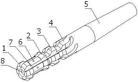
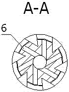
[0021] Such as Figure 1 to Figure 4 One of them shows: a reaming drill bit, including a first cutting edge 1, a second cutting edge 2, a third cutting edge 3, a fourth cutting edge 4, a Morse taper shank 5, an outer cooling hole 6, and a cutting groove 7. Central cooling hole 8; the first cutting edge 1 is arranged on the front end face of a reaming drill; the second cutting edge 2 is arranged behind the first cutting edge...


PUM


Abstract

The invention discloses a broaching bit comprising first cutting edges, second cutting edges, third cutting edges, fourth cutting edges, a Morse taper shank, outer side face cooling holes, cutting grooves and a center cooling hole. Through the center cooling hole and the outer side face cooling holes of the broaching bit, the cutting edges bearing most of cutting resistance and heat is cooled to the maximum extent, the phenomenon that a nickel-base heat resistant alloy is melted and attached to a drilling tool is avoided, and the service life of the bit is prolonged. The broaching bit is provided with the second cutting edges, the third cutting edges and the fourth cutting edges so that a broached hole and a reamed hole can be formed at a time, the production efficiency is improved, and the roughness of the hole surfaces is higher through the multiple cutting edges. The broaching bit is provided with the Morse taper shank, the interchangeability of existing machining equipment is guaranteed, and the application range is wider.

Description

technical field [0001] The invention relates to the technical field of mechanical cutting processing equipment, in particular to a reaming drill bit. Background technique [0002] At present, in mechanical processing, it is often encountered that the hole needs to be reamed due to the design or repair of the mechanical cooperation. The usual processing method is to use a larger drill bit to re-drill the original hole position. Many types of drilling tools have been produced, such as deep hole reaming and drilling combination devices, high-speed cutting and flat bottom hole drilling tools, etc., but in the processing of cemented carbide, especially in the reaming of nickel-based heat-resistant alloys, due to Existing ordinary drill bits are mostly made of high-speed steel. In the reaming drill of nickel-based heat-resistant alloys, the cutting temperature of the drill bit is often very high, resulting in heat treatment phenomena such as annealing of the drilled part of the dr...

Claims


Application Information

Patent Timeline
IPC IPC(8): B23B51/00B23B51/06
Inventor 黄海霞
Owner 上海汉硕机械技术有限公司
Learn More