Large workpiece clamping device and clamping system

A workpiece clamping and large-scale technology, applied in the field of tooling and fixtures, can solve the problems of relative displacement between the clamping surface and the workpiece surface, lack of safety, poor flexibility, etc., to achieve convenient and flexible adaptive adjustment, increase the effective contact area, and avoid local damage Effect

Active Publication Date: 2017-11-03
重庆真测科技股份有限公司 +2
View PDF20 Cites 6 Cited by
  • Summary
  • Abstract
  • Description
  • Claims
  • Application Information

AI Technical Summary

Problems solved by technology

[0002] With the rapid development of science and industry technology, industrial manufacturing technology has made revolutionary breakthroughs, and the performance of corresponding processing and manufacturing, testing, experiment and other equipment has become stronger and stronger, but the clamping process of supporting workpieces or parts has not Adaptive progress has been made. With the implementation of various large-scale projects, the clamping requirements for processing, testing, moving, and fixing of large parts and components have become increasingly prominent. The existing workpiece clamping methods are difficult to fully meet the requirements.
For example, when the entire large cylindrical workpiece is clamped, fixed, moved, hoisted, and overall rotated, there are many common problems: inconvenient operation, poor flexibility, lack of safety, poor precision, high cost, and low efficiency; for some workpiece surfaces The clamping method in places with local protrusions may cause damage to the surface of the workpiece, or there may be uneven clamping force, and relative displacement between the clamping surface and the surface of the workpiece; in order to solve such problems, it is necessary to conduct in-depth research explore

Method used


Image

  • Large workpiece clamping device and clamping system
  • Large workpiece clamping device and clamping system
  • Large workpiece clamping device and clamping system

Examples


Embodiment Construction

[0027] The technical solutions in the present invention will be further described below in conjunction with the accompanying drawings and embodiments.

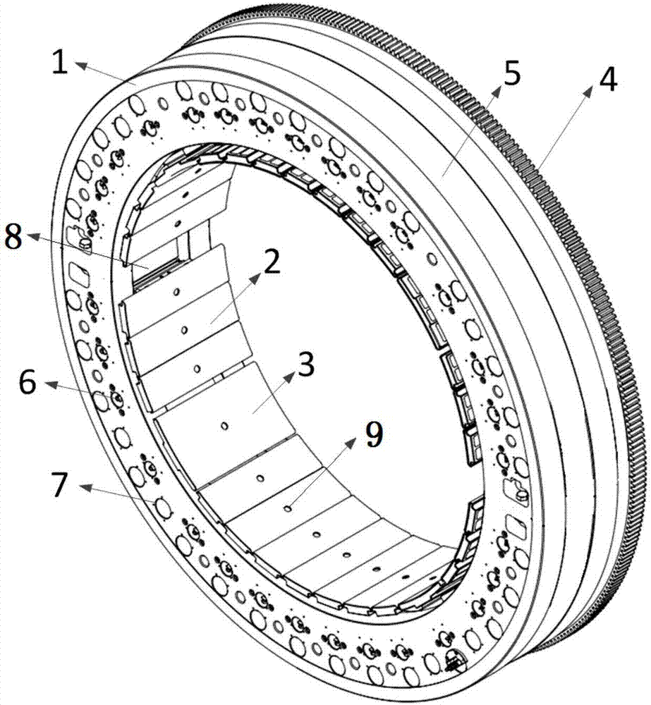
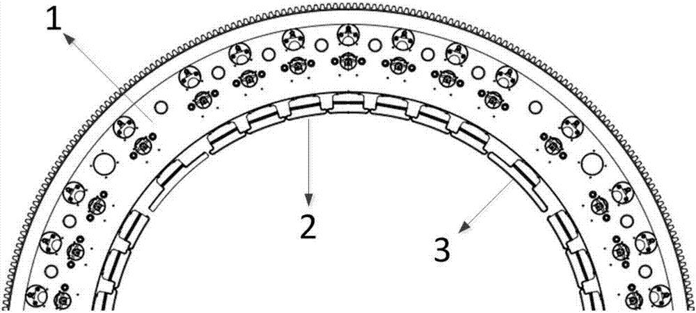
[0028] A workholding device such as figure 1 , figure 2 As shown, it includes a circular clamp body 1, and an installation groove 8 is provided on the inner ring of the clamp body 1 to install a detachable clamping unit. The number of clamping units that can be installed at the same time is 30 to 48; the clamp The main body 1 is provided with a transmission tooth 4 on the outer ring side of its ring for meshing with the external gear; a groove 5 is provided in the middle of the outer arc surface of the fixture body 1 along its ring to be suitable for clamping of external devices , hoisting, positioning, or guidance when the fixture body rotates; a number of mounting holes 6 and guide holes 7 are provided on one side of the fixture body 1; the mounting holes 6 are used for mounting and fixing the clamping unit; the guide hole...


PUM


Abstract

The invention provides a large workpiece clamping device. The large workpiece clamping device comprises a circular clamp body. A mounting groove is formed in the inner ring of the clamp body so that multiple detachable clamping units can be mounted. Each clamping unit comprises a clamping execution device and a clamping drive device. Each clamping drive device is connected with the corresponding clamping execution device and used for driving the corresponding clamping execution device to move in the axial direction and/or the radial direction of a ring of the clamp body. The clamping execution devices are circumferentially distributed along the inner ring of the clamp body. Each clamping drive device comprises a drive device connecting portion fixedly connected with the clamp body. The invention further provides a large workpiece clamping system which comprises the large workpiece clamping device and a bearing platform. Supporting bases are arranged on the bearing platform in parallel. The supporting bases are provided with rolling bearing grooves matched with the outer edge of the clamp body. The large workpiece clamping device and the large workpiece clamping system have the beneficial effects that floating clamping is achieved; the center position of a workpiece does not need to be adjusted repeatedly when the workpiece is clamped; an extra auxiliary supporting structure is not needed; and the clamping efficiency is improved.

Description

technical field [0001] The invention relates to the field of fixtures, in particular to a large workpiece clamping device and a clamping system. Background technique [0002] With the rapid development of science and industry technology, industrial manufacturing technology has made revolutionary breakthroughs, and the performance of corresponding processing and manufacturing, testing, experiment and other equipment has become stronger and stronger, but the clamping process of supporting workpieces or parts has not Adaptive progress has been made. With the implementation of various large-scale projects, the clamping requirements for processing, testing, moving, and fixing of large parts and components as a whole have become increasingly prominent. It is difficult for the existing workpiece clamping methods to fully meet the requirements. For example, when the entire large cylindrical workpiece is clamped, fixed, moved, hoisted, and overall rotated, there are many common probl...

Claims


Application Information

Patent Timeline
Patent Type & Authority Applications(China)
IPC IPC(8): B23Q3/06
CPCB23Q3/062Y02P70/10
Inventor 张钦诚王珏刘荣谭辉刘丰林郭鹏辉陈海张磊杨荣东苏志军吴育锋关桢
Owner 重庆真测科技股份有限公司
Why Eureka
Try Eureka