Self-tightening end surface driving chuck

A drive chuck and self-tightening technology, applied in the field of drive devices and self-tightening end-face drive chucks, can solve the problems of low processing efficiency, influence of coaxiality, and inability to increase output, and achieve simple, convenient and stable maintenance. Good sex, no auxiliary device effect

Pending Publication Date: 2017-11-03
西安铁路职业技术学院
View PDF8 Cites 3 Cited by
  • Summary
  • Abstract
  • Description
  • Claims
  • Application Information

AI Technical Summary

Problems solved by technology

[0003] In mechanical processing, the clamping power of the chuck depends on the pull rod to connect the hydraulic device or the pneumatic device. For small-scale production, a hydraulic station or a pneumatic room needs to be established, which artificially causes a certain economic burden; in addition, the processing of long-axis parts usually has The part held by the chuck cannot be machined and needs to be processed twice, so it will have a certain impact on the coaxiality
If you want to ensure the coaxiality, you need the master worker to repeatedly debug and calibrate, which is not only time-consuming and laborious, but also the output cannot be increased, and the processing efficiency is low.

Method used


Image

  • Self-tightening end surface driving chuck
  • Self-tightening end surface driving chuck

Examples


Embodiment Construction

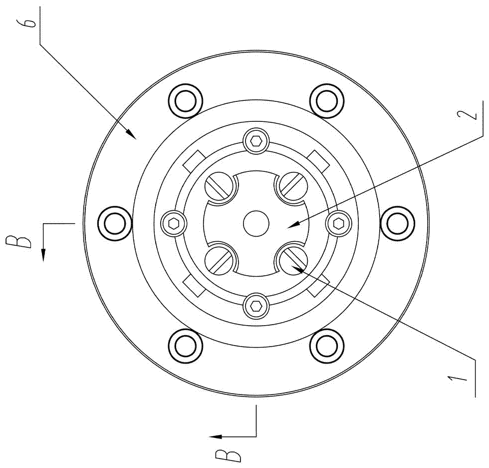
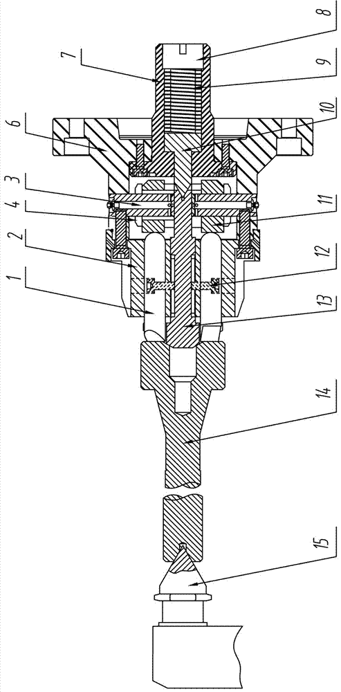
[0023] The self-tightening end face drive chuck of the present invention comprises a tailstock top 15, a chuck top 13, a guide seat 2, a spring top seat 7 and a connection plate 6, the tailstock top 15 and the chuck top 13 are arranged oppositely, and the guide seat 2 A guide hole is provided, the connecting disc 6 is fixedly connected with the spindle end of the machine tool, the central axis of the tailstock top 15 coincides with the central axis of the chuck top 13; the chuck top 13 passes through the guide hole and is connected with a spring top 10 , the spring top 10 is slidingly arranged in the spring top seat 7, and one end is elastically connected to the spring top seat 7 through an elastic device, and the other end protrudes from the spring top seat 7 toward the chuck top 13;

[0024] Several drive pins 1 are evenly distributed around the chuck top 13 in the guide seat 2, and the drive pins 1 are connected to the spring top seat 7 through an adjustment device, and the ...


PUM


Abstract

The invention relates to a driving clamping chuck, in particular to a driving device without a hydraulic station or a pneumatic room used as a power source, is used for high-precision and high-coaxiality non-circular curve and complex shape machining of rotary parts, and specifically relates to a self-tightening end surface driving chuck. The chuck comprises a tailstock tip, a chuck tip, a guide seat, a spring tip seat and a connecting disk; the tailstock tip is opposite to the chuck tip; a guide hole is formed in the guide seat; the connecting disk is fixedly connected with the output end of an oil cylinder of a machine tool; and the central axis of the tailstock tip is overlapped with the central axis of the chuck tip. The chuck tip is used for centering, the tailstock tip clamps a workpiece for matching with forwards pushing and guarantees the concentricity of two ends of the workpiece, the problem about coaxiality of a precision part due to secondary clamping in a traditional process scheme can be effectively solved, the chuck is simple in structure, free of auxiliary devices and simple and convenient to maintain.

Description

technical field [0001] The invention relates to a driving and clamping chuck, in particular to a driving device without a hydraulic station or a pneumatic room as a power source; it is used for processing non-circular curves and complex shapes with high precision and high coaxiality of rotary parts, and specifically relates to a A self-tightening face drive chuck. Background technique [0002] In the processing of rotary parts, the drive clamping chucks include hydraulic control chucks, pneumatic control chucks and manual clamping chucks. Both hydraulic chucks and pneumatic chucks are based on hydraulic stations or pneumatic rooms. Although all can be automatically aligned and clamped, the economic cost is increased for small-scale production and processing. [0003] In mechanical processing, the clamping power of the chuck depends on the pull rod to connect the hydraulic device or the pneumatic device. For small-scale production, a hydraulic station or a pneumatic room ne...

Claims


Application Information

Patent Timeline
Patent Type & Authority Applications(China)
IPC IPC(8): B23Q3/12B23Q1/76
CPCB23Q1/76B23Q3/12
Inventor 刘宏利刘明玺丁万霞杨山岭冯小庭潘伟骈立
Owner 西安铁路职业技术学院
Why Eureka
Try Eureka