Barstock clamping robot arm

A technology for robotic arms and bars, applied in the direction of manipulators, program-controlled manipulators, chucks, etc., can solve the problems of easily damaged bar surfaces, difficulty in adjusting the critical value of clamping force, and changes in clamping force, so as to ensure quality and avoid The surface of the bar is damaged and the effect of preventing the bar from loosening

Inactive Publication Date: 2017-11-03
FOSHAN JIELAN ROBOT CO LTD
View PDF0 Cites 10 Cited by
  • Summary
  • Abstract
  • Description
  • Claims
  • Application Information

AI Technical Summary

Problems solved by technology

Bar clamping is one of the important applications of the robot arm. If the clamping claws of the current robot arm are adjusted too tightly, the surface of the bar will be easily damaged. If the clamping force is insufficient, the bar will easily become loose. The critical value of clamping force is usually difficult to adjust, and even after precise adjustment, the clamping force will still change after many uses

Method used


Image

  • Barstock clamping robot arm

Examples


Embodiment Construction

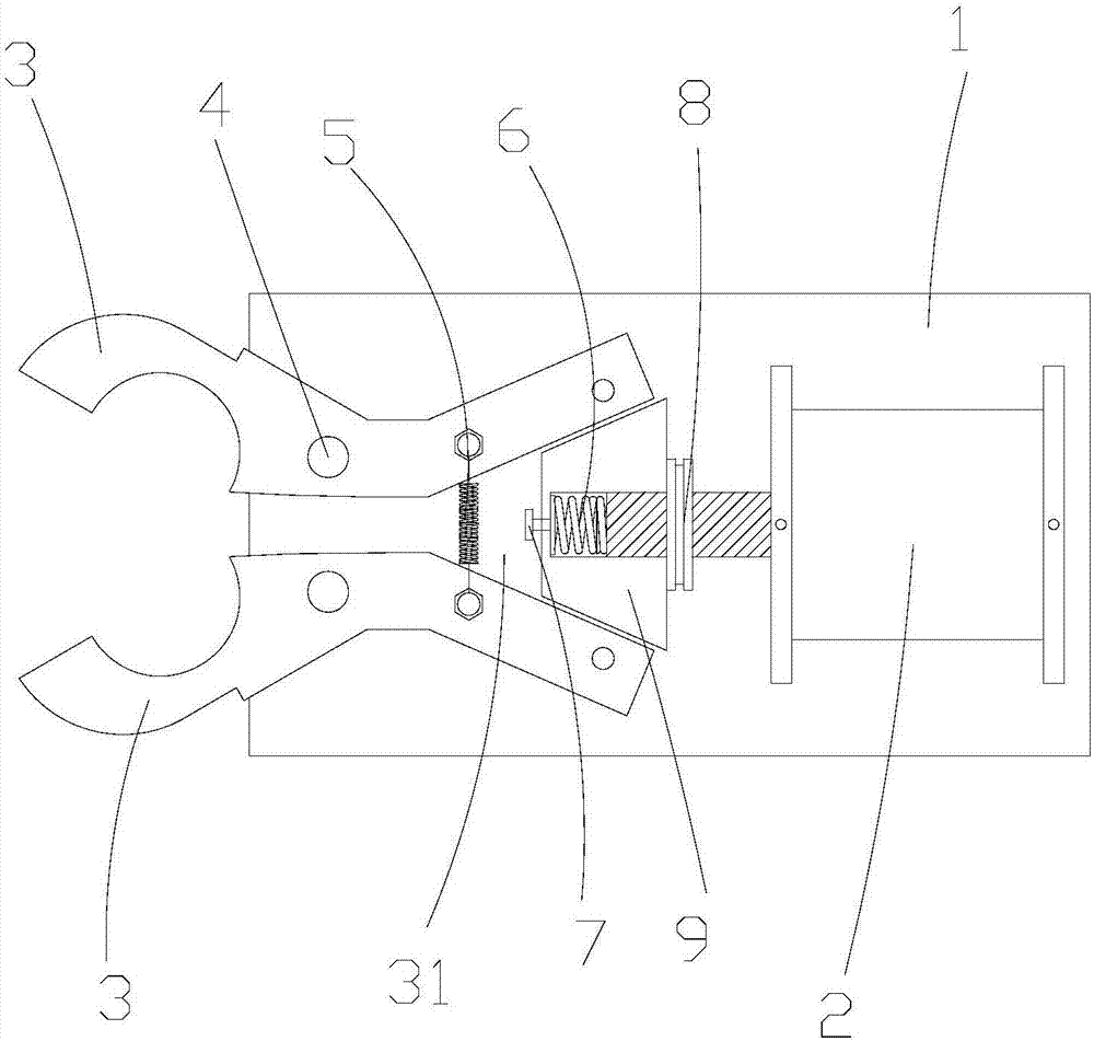
[0011] The present invention is described in detail below in conjunction with accompanying drawing and specific embodiment:

[0012] Such as figure 1 A bar clamping robot arm is shown, including a bearing seat 1, a driving cylinder 2, a clamping claw 3, a rotating shaft 4, a tension spring 5, a spring 6, a limit lock sleeve 8 and a trapezoidal block 9, and two clamping claws 3 The front end of the bearing seat 1 is installed by rotating the rotating shaft 4 correspondingly, and the two ends of the tension spring 5 are respectively connected to the rear ends of the two clamping claws 3, and the rear ends of the two clamping claws 3 form a fan-shaped area 31 with a small inside and a large outside. The cylinder body of the driving cylinder 2 is fixedly installed on the rear end of the bearing seat 1, the shape of the trapezoidal block 9 is set corresponding to the shape of the fan-shaped area 31, the outer end of the trapezoidal block 9 is provided with a mounting hole, the spri...


PUM


Abstract

The invention discloses a bar material clamping robot arm, which includes a bearing seat, a driving cylinder, a clamping claw, a rotating shaft, a tension spring, a spring, a limit lock sleeve and a trapezoidal block. The two clamping claws are installed and carried by corresponding rotation of the rotating shaft The front end of the seat, and the two ends of the tension spring are respectively connected to the rear ends of the two clamping claws. The rear ends of the two clamping claws form a fan-shaped area with a small inside and a large outside. The two ends of the spring act on the trapezoidal block and the drive respectively. On the piston rod of the cylinder, the limit lock sleeve is sleeved and installed on the piston rod of the drive cylinder, and the front end of the piston rod of the drive cylinder is provided with a limit protrusion that matches the limit lock sleeve. It is also fixedly installed on the outer end of the trapezoidal block. By setting the piston rod compression spring, it is possible to avoid damage to the surface of the bar due to too tight clamping force, and at the same time avoid the phenomenon of loosening of the bar due to insufficient clamping force. The clamping force of the claws is controlled within a reasonable range to ensure the quality of the product.

Description

Technical field: [0001] The invention belongs to the technical field of intelligent automation robot equipment, and in particular relates to a bar clamping robot arm. Background technique: [0002] A robot is a machine device that performs work automatically. It can accept human command, run pre-programmed programs, and act according to principles formulated with artificial intelligence technology. Its task is to assist or replace the work of human work. Bar clamping is one of the important applications of the robot arm. If the clamping claws of the current robot arm are adjusted too tightly, the surface of the bar will be easily damaged. If the clamping force is insufficient, the bar will easily become loose. The critical value of clamping force is usually difficult to adjust, and even after precise adjustment, the clamping force will still change after many uses. Invention content: [0003] The technical problem to be solved by the present invention is to provide a ro...

Claims


Application Information

Patent Timeline
Patent Type & Authority Applications(China)
IPC IPC(8): B25J9/10B25J15/00
CPCB25J9/1015B25J15/0038
Inventor 胡玲
Owner FOSHAN JIELAN ROBOT CO LTD
Why Eureka
Try Eureka