
Multifunctional door lock

A multi-functional, door lock technology, used in building locks, door/window accessories, handle connections, etc., can solve the problem of easy residual moisture in the handle lock handle, and achieve the improvement of sensory experience, advanced technical ideas, and reasonable technical solutions. Effect

Inactive Publication Date: 2017-11-03
天津厚进机械租赁有限公司
View PDF0 Cites 0 Cited by
  • Summary
  • Abstract
  • Description
  • Claims
  • Application Information

AI Technical Summary

Problems solved by technology

[0003] The present invention aims at the technical defects of the prior art, and provides a multifunctional door lock to solve the technical problem that the hand lock handles used in the toilet are prone to residual moisture in the prior art

Method used


Image

  • Multifunctional door lock

Examples


Embodiment 1

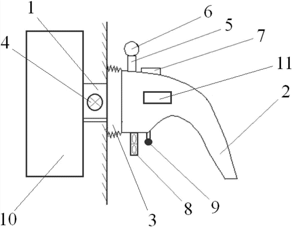
[0022] A multifunctional door lock, including a connecting shaft 1, a handle 2, a PTC thermistor 3, a power supply 4, a disinfectant storage tank 5, a nozzle 6, a switch 7, a fan 8, an ultraviolet lamp 9, a lock cylinder 10, and an ultrasonic generator device 11, wherein one end of the connecting shaft 1 is connected to the lock cylinder 10, and the other end is fixedly connected to the handle 2, and the PTC thermistor 3 is in the shape of a hollow disk, and the PTC thermistor 3 is sleeved on the connecting shaft 1 and is connected with the The handle 2 fits together, the power supply 4 is built into the connecting shaft 1, the disinfectant storage tank 5 is fixedly connected to the handle 2, the nozzle 6 is connected to the disinfectant storage tank 5 through a pipeline, and the nozzle 6 passes through the first A wire is connected to the power supply 4, the switch 7 is connected in series on the first wire, the fan 8 is fixedly connected to the handle 2, the blowing direction...

Embodiment 2

[0029] A multifunctional door lock, including a connecting shaft 1, a handle 2, a PTC thermistor 3, a power supply 4, a disinfectant storage tank 5, a nozzle 6, a switch 7, a fan 8, an ultraviolet lamp 9, a lock cylinder 10, and an ultrasonic generator device 11, wherein one end of the connecting shaft 1 is connected to the lock cylinder 10, and the other end is fixedly connected to the handle 2, and the PTC thermistor 3 is in the shape of a hollow disk, and the PTC thermistor 3 is sleeved on the connecting shaft 1 and is connected with the The handle 2 fits together, the power supply 4 is built into the connecting shaft 1, the disinfectant storage tank 5 is fixedly connected to the handle 2, the nozzle 6 is connected to the disinfectant storage tank 5 through a pipeline, and the nozzle 6 passes through the first A wire is connected to the power supply 4, the switch 7 is connected in series on the first wire, the fan 8 is fixedly connected to the handle 2, the blowing direction...


PUM


Abstract

The invention provides a multifunctional door lock. In this technical solution, in order to ensure the handle is dry, a fan is placed on the handle, and an ultrasonic generator is built in the handle, and the effect of ultrasonic waves is used to strengthen the protection against water droplets on the handle. Disturb and increase the surface area of ​​water droplets, and cooperate with the fan to increase the drying speed. On the other hand, in order to alleviate the growth of microorganisms, the present invention adds a disinfectant injection module and an ultraviolet disinfection module, which effectively improves the cleanliness and sterility of the handle. In addition, the present invention aims at the problem that the low temperature of the handle of the handle lock affects the comfort, and a PTC thermistor is installed at the position where the handle is attached, and the characteristic of constant temperature heating of the PTC thermistor is used to ensure that the temperature of the handle is close to the problem of the human body, thereby Enhance the sensory experience of users. The invention has advanced technical thinking, reasonable technical scheme and great market prospects.

Description

technical field [0001] The invention relates to the technical field of door components, in particular to a multifunctional door lock. Background technique [0002] The handle lock is a necessary part of indoor doors, and its structure and design specifications directly affect the comfort of use. In view of the different environments in which the handle locks are located, there are also differences in their design details. For example, the handle locks used in places with flammable materials should not easily generate static electricity and try to avoid using conductive materials; while the handle locks used in children's rooms It should have a decent height and the material should be as soft as possible, etc. In the prior art, the handle locks used in toilets are generally not designed for adaptability. During use, water droplets often remain on the handles due to grasping the handles with hands that have not yet dried after washing, which brings discomfort to the subsequen...

Claims


Application Information

Patent Timeline
Patent Type & Authority Applications(China)
IPC IPC(8): E05B1/00E05B3/00
CPCE05B1/0069E05B3/00
Inventor 李胜蕊
Owner 天津厚进机械租赁有限公司
Learn More