High-efficiency sewage source heat pump capable of being cleaned easily

A sewage source heat pump and easy-to-clean technology, applied in the field of heat pumps, can solve problems such as low heat transfer coefficient, difficult cleaning, deposition, etc., and achieve the effect of improving heat transfer coefficient, good directionality, and improved capacity

Pending Publication Date: 2017-11-03
东莞市康源节能科技有限公司
View PDF7 Cites 0 Cited by
  • Summary
  • Abstract
  • Description
  • Claims
  • Application Information

AI Technical Summary

Problems solved by technology

[0003] The existing sewage source heat pump system usually places the evaporator in a waterless tank, which has problems such as blockage, deposition, low heat transfer coefficient, and difficult cleaning. The defects are obvious, and a solution is urgently needed

Method used


Image

  • High-efficiency sewage source heat pump capable of being cleaned easily
  • High-efficiency sewage source heat pump capable of being cleaned easily
  • High-efficiency sewage source heat pump capable of being cleaned easily

Examples


Embodiment 1

[0033] Sewage source heat pump, heat pump waste heat recovery.

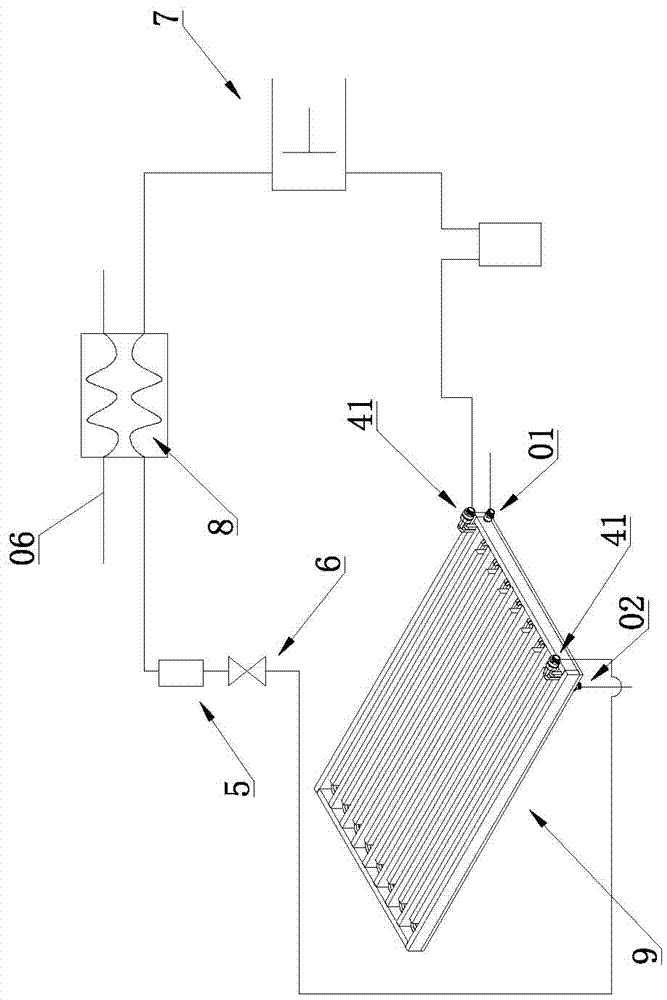
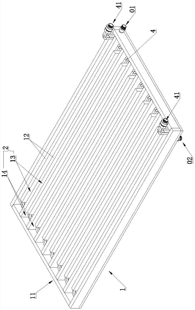
[0034] Such as Figure 1 to Figure 5 As shown, a high-efficiency and easy-to-clean sewage source heat pump includes an evaporator 9, a condenser 8, a compressor 7 connected to the evaporator 9 and the condenser 8, a refrigerant throttling device 6 connected to the evaporator 9, and a The refrigerator filter 5 connected to the refrigerant throttling device 6, the refrigerator filter 5 is connected to the condenser 8, the evaporator 9 includes a water tank 1 and a refrigerant pipeline 4, and the water tank 1 is provided with a guide for guiding The water flow channel 2 through which the sewage flows in a detour, the refrigerant pipeline 4 is laid on the water flow channel 2, and when the sewage with heat passes through the water flow channel 2, the refrigerant in the refrigerant pipeline 4 absorbs the heat of the sewage.

[0035] Sewage produced by shampoo beds, bathrooms, etc. flows into the water flow channel 2,...

Embodiment 2

[0048] Compound waste heat recovery and multi-stage continuous heating.

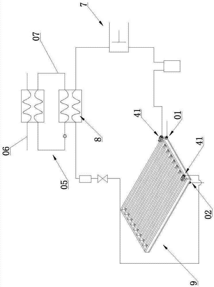
[0049] Such as Figure 6 to Figure 9 As shown, the difference between the second embodiment and the first embodiment is that: the water flow channel 2 is also laid with a heat exchange pipe 3 for circulating tap water. When in use, the sewage with heat flows through the water flow channel 2 to exchange The tap water flowing in the hot pipe 3 absorbs the heat of the sewage. The heat exchange pipe 3 is provided with a waste heat recovery water inlet 31 and a waste heat recovery water outlet 32 ​​. Tap water is passed to the heat exchange pipe 3, and when the tap water flows in the heat exchange pipe 3, it absorbs the heat of the sewage in the water flow channel 2, thereby recovering the heat of the sewage. In this embodiment, the refrigerant in the refrigerant pipe 4 and the tap water in the heat exchange pipe 3 are used to absorb the heat of the sewage to realize composite waste heat recovery.

[0050]...

Embodiment 3

[0053] Composite waste heat recovery, storage and reheating.

[0054] Such as Figure 10 to Figure 11 As shown, the difference between the third embodiment and the second embodiment is that a water storage tank 08 is also provided, and the delivery pipeline 38 is connected to the water storage tank 08 . The tap water absorbs the heat of the sewage in the water flow channel 2, enters the water storage tank 08 through the delivery pipe 38 for storage, and then is further heated to the set temperature by the condenser 8.


PUM


Abstract

The invention relates to the technical field of heat pumps, in particular to a high-efficiency sewage source heat pump capable of being cleaned easily. The sewage source heat pump comprises an evaporator, a condenser, a compressor, a refrigerating fluid throttling device and a refrigerator filter. The evaporator comprises a water tank and refrigerating fluid pipelines. A water flow channel used for guiding sewage to achieve circuitous flow is formed in the water tank. The refrigerating fluid pipelines are laid in the water flow channel. When sewage with heat passes through the water flow channel, refrigerating fluid in the refrigerating fluid pipelines can absorb the sewage heat. According to the high-efficiency sewage source heat pump capable of being cleaned easily, the sewage can be guided to achieve circuitous flow by the adoption of the water flow channel in the water tank, then the refrigerating fluid pipelines laid in the water flow channel are used for absorbing waste heat of the sewage, the sewage in the water flow channel is subjected to waste heat recovery, the flowing directionality of the sewage is good through the circuitous water flow channel, the sewage flowing velocity v can be controlled and increased conveniently, the coefficient of heat transfer is increased, and by increasing the sewage flowing velocity, heating capacity of the sewage source heat pump is improved; and meanwhile the capacity of carrying away dirt by the sewage is improved, and the effects of being high in efficiency and easy to clean are achieved.

Description

technical field [0001] The invention relates to the technical field of heat pumps, in particular to an efficient and easy-to-clean sewage source heat pump. Background technique [0002] The recovery and reuse of low-grade waste fluid energy has always been a research focus in the field of energy conservation. The biggest problem of low-grade waste fluid energy recovery is fouling, deposition, and a significant reduction in heat transfer coefficient. Especially for waste water source heat pump systems where waste fluid energy is recovered, it is even more difficult to clean the heat exchanger. For large-scale high-grade sewage fluid systems, this problem can be solved through filtration and other treatment methods. For small and medium-sized low-grade sewage systems such as aquaculture, filtration and other treatment methods are uneconomical, bulky, and heat loss during treatment. [0003] The existing sewage source heat pump system usually places the evaporator in a waterle...

Claims


Application Information

Patent Timeline
Patent Type & Authority Applications(China)
IPC IPC(8): F25B1/00F25B30/06F25B41/06F25B41/30
CPCF25B1/00F25B30/06F25B41/30Y02P80/15
Inventor 张加振
Owner 东莞市康源节能科技有限公司
Why Eureka
Try Eureka