
Method for installing thermocouple on inner wall of shell of high temperature container

A high-temperature container and thermocouple technology, which is used in thermometer parts, instruments, thermometers, etc., can solve the problems of inability to measure the inner wall temperature more realistically, affecting fluid flow, and high damage rate of ultra-fine thermocouples

Active Publication Date: 2019-07-30
STATE NUCLEAR HUAQING BEIJING NUCLEAR POWER TECH R & D CENT +1
View PDF5 Cites 0 Cited by
  • Summary
  • Abstract
  • Description
  • Claims
  • Application Information

AI Technical Summary

Problems solved by technology

Due to the existence of the heat collecting block, the fluid flow in the temperature measurement area of ​​the inner wall of the container is affected, so that the measuring device itself affects the local flow of the fluid in the container, and it is impossible to measure the inner wall temperature more realistically.
Furthermore, due to the heat storage of the heat collecting block and other reasons, the response time of the thermocouple temperature measurement will increase, which will affect the accuracy and effect of the transient wall temperature measurement.
In addition, the thermocouple is welded to the heat collecting block by means of laser welding, etc., the instantaneous temperature of the welding process is high, the damage rate of the ultra-fine thermocouple is high during the welding process, and the operation feasibility of the ultra-fine thermocouple is very low

Method used


Image

  • Method for installing thermocouple on inner wall of shell of high temperature container
  • Method for installing thermocouple on inner wall of shell of high temperature container
  • Method for installing thermocouple on inner wall of shell of high temperature container

Examples


Embodiment Construction

[0032] While the present invention will be fully described with reference to the accompanying drawings containing preferred embodiments of the invention, it should be understood before proceeding that those skilled in the art may modify the invention described herein while obtaining the technical effects of the present invention. Therefore, it should be understood that the above description is a broad disclosure for those skilled in the art, and its content is not intended to limit the described exemplary embodiments of the present invention.

[0033] Additionally, in the following detailed description, for purposes of explanation, numerous specific details are set forth in order to provide a thorough understanding of the embodiments disclosed herein. It may be evident, however, that one or more embodiments may be practiced without these specific details. In other instances, well-known structures and devices are shown in diagrammatic form to simplify the drawings.

[0034] Su...


PUM

PropertyMeasurementUnit
sizeaaaaaaaaaa
surface roughnessaaaaaaaaaa
depthaaaaaaaaaa

Abstract

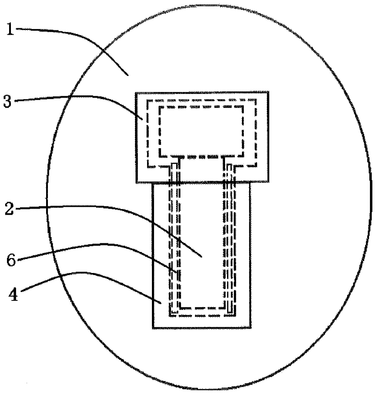
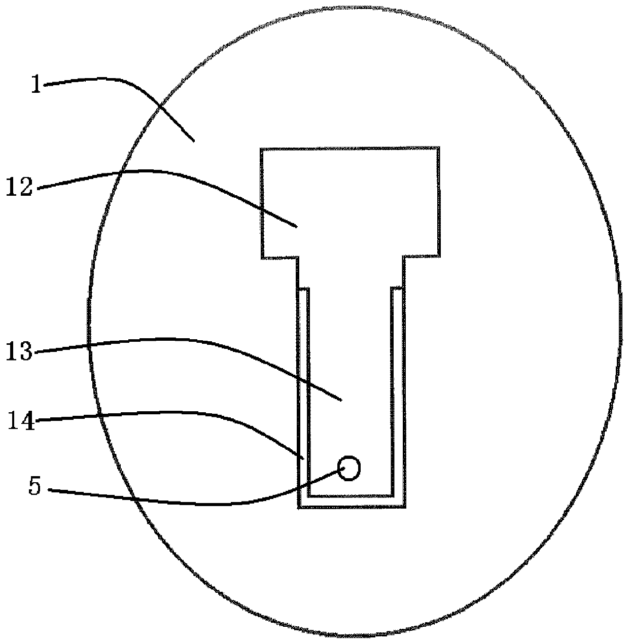
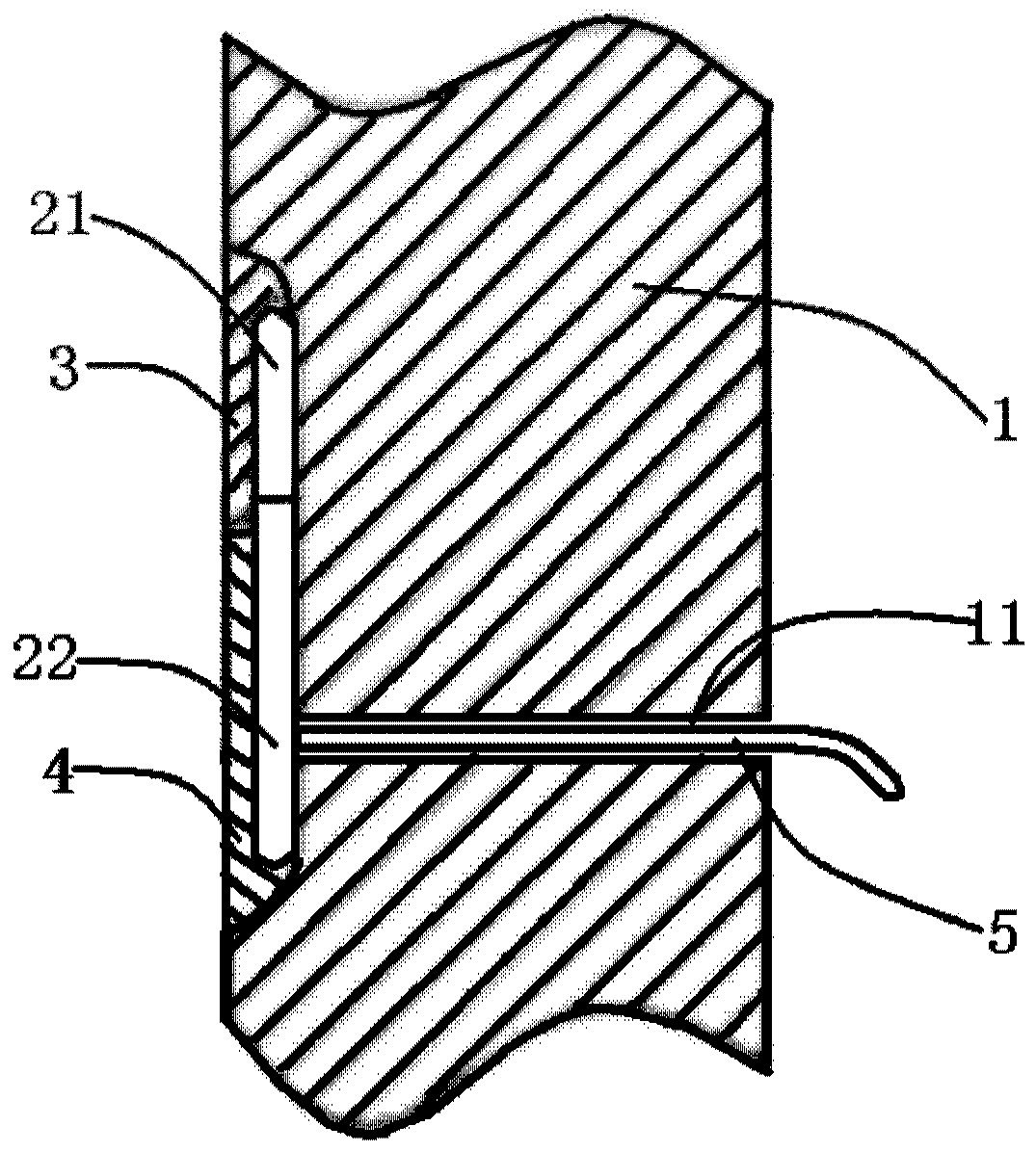
A method for installing a thermocouple on an inner wall of a shell of a high-temperature container, comprising the steps of: forming a groove on the inner wall of the shell of a high-temperature container, the groove including a first groove portion and a second groove portion; The surrounding of the first groove part is heated to a predetermined temperature; the thermocouple is placed in the groove, wherein the induction part of the thermocouple is located in the first groove part, and the wiring part electrically connected with the induction part is located in the second groove part Apply the brazing material in the molten state in the first groove part; the brazing material is cooled and solidified to form a brazing heat conducting block, so that the brazing heat conducting block connects the induction part of the thermocouple and the wall surface of the first groove part; grinding The brazing heat conduction block makes the outer surface of the braze heat conduction block flush with the inner wall surface of the shell; and the fixing pressing piece is fixed in the second groove part corresponding to the wiring part. By using this thermocouple, the temperature of the inner wall surface of the container can be measured quickly, accurately and with high precision without affecting the original flow state of the fluid in the container.

Description

technical field [0001] The invention relates to a high-temperature container, and more specifically, relates to a method for installing miniature thermocouples on the inner wall of the casing of the high-temperature container. Background technique [0002] In order to accurately measure the temperature of the inner wall of the high-temperature container, it is necessary to minimize the temperature measurement response time of the temperature measuring device and the influence of the temperature measuring device on the fluid flow field of the inner wall of the container. For this reason, it is necessary to install ultra-fine armored thermocouples on the inner wall of the high-temperature container. The installation process must ensure the smoothness of the inner wall of the temperature measurement place, without affecting the flow and temperature distribution of the fluid in the high-temperature container. Robust temperature measuring thermocouples are required to achieve tem...

Claims


Application Information

Patent Timeline
Patent Type & Authority Patents(China)
IPC IPC(8): G01K1/14G01K7/02
CPCG01K1/143G01K7/02
Inventor 王嘉鹏李鹏飞田芳王绪伟
Owner STATE NUCLEAR HUAQING BEIJING NUCLEAR POWER TECH R & D CENT
Learn More