
A water flow induced vibration energy harvester

An energy harvester and vibration-induced technology, which is applied in the direction of piezoelectric effect/electrostrictive or magnetostrictive motors, electromechanical devices, electrical components, etc., can solve the problem of power supply of the monitoring system, which has not been well solved and has not been obtained. Problems such as large-scale promotion and application, to achieve the effect of simple structure, high reliability, and good incentive effect

Active Publication Date: 2019-03-26
ZHEJIANG NORMAL UNIVERSITY
View PDF5 Cites 0 Cited by
  • Summary
  • Abstract
  • Description
  • Claims
  • Application Information

AI Technical Summary

Problems solved by technology

Although some of the monitoring methods proposed at present are relatively mature in technology, they have not been popularized and applied in a large area. One of the main reasons is that the power supply problem of the monitoring system has not been well resolved.

Method used


Image

  • A water flow induced vibration energy harvester
  • A water flow induced vibration energy harvester
  • A water flow induced vibration energy harvester

Examples


Embodiment Construction

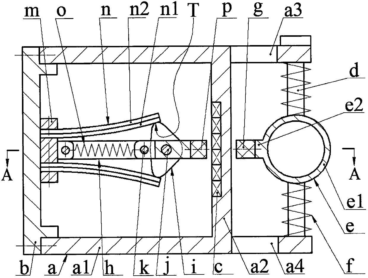
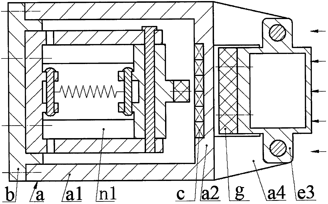
[0013] The end of the side wall al of the housing a is fitted with an end cover b via screws, the inner side of the bottom wall a2 of the housing a is inlaid with a coil c, the outer side of the bottom wall a2 is provided with an upper ear plate a3 and a lower ear plate a4, two long pins The two ends of d are respectively fixed on the upper ear plate a3 and the lower ear plate a4; the turbulent body e consists of a hollow cylinder e1, a boss e2 placed on the outer surface of the cylinder e1 and side plates placed at both ends of the cylinder e1 The side plate e3 is set on the long pin d, and each long pin d is covered with two pressure springs f, which are pressed on the upper and lower sides of the side plate e3; the boss e2 is equipped with a magnetic The strip g and the magnetic strip g are installed close to the bottom wall a2 of the shell a; the frame h is provided with a frame bottom plate h1, two inner ear plates h2 and two outer ear plates h3, and the frame bottom plate...


PUM


Abstract

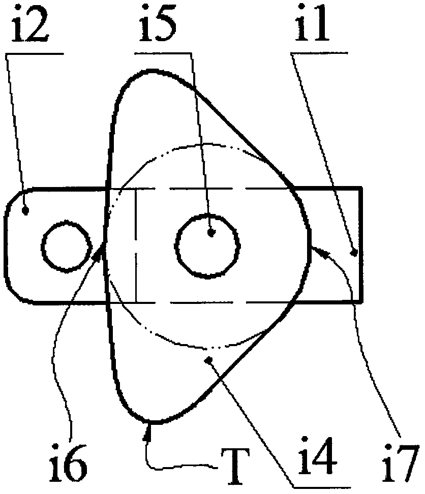
The present invention relates to a water flow-induced vibration energy accumulator and belongs to the technical field of electric power generation. An end part of a side wall of a shell body is provided with an end cap, a wire coil is embedded inside a bottom wall, upper and lower ear plates are arranged on an outer side of the bottom wall, and a long pin is fixed on the upper and lower ear plates; a flow disturbing body consists of a column body, a boss and a side plate; the side plate sleeves the long pin, and two pressure springs sleeving the long pin are pressed on upper and lower sides of the side plate; a magnetic strip is mounted on the boss, the magnetic strip is installed near a bottom wall of the shell body; a frame is provided with a frame bottom plate as well as inner and outer ears plates, the bottom plate of the frame is mounted on the end cap, a rocker arm of an exciter is provided with a rocker ear plate and a cam, a magnetic block is mounted on the rocker arm, the rocker arm sleeves a rotary shaft, two ends of the rotary shaft are fixed on the outer ear plate, pin shafts are mounted on the inner ear plate and the ear plate of the rocker arm, two ends of a tension spring are connected onto the pin shaft, energy transducers are mounted on an upper side and a lower side the frame bottom plate, each energy transducer is formed by bonding a substrate and a piezoelectric membrane, end parts of the energy transducers are butted against a vertex of the cam, a cam contour curve comprises two arc contours that are concentric with an axle hole, and the energy transducers are of a flat and straight structure before installation.

Description

technical field [0001] The invention belongs to the technical field of power generation, and in particular relates to a water flow-induced vibration energy harvester for powering a river monitoring system. Background technique [0002] There are thousands of rivers all over the territory of our country. In recent years, due to insufficient treatment of industrial wastewater, soil erosion, and improper use of pesticides and fertilizers, most rivers have been polluted to a certain extent. Nearly 1 / 4 of the rivers or river sections cannot meet basic irrigation due to pollution. need. In addition, because the current flood control facilities for small and medium-sized rivers in many areas are not perfect, or even do not have any flood control facilities, when the flood season comes, it may cause dangers such as embankment failure or flooding, directly threatening the lives and property safety of people along the coast. Therefore, river monitoring has been highly valued by rele...

Claims


Application Information

Patent Timeline
Patent Type & Authority Patents(China)
IPC IPC(8): H02N2/18H02K35/02
CPCH02K35/02H02N2/186
Inventor 张忠华刘立博柴君凌王鸿云郭健安阚君武
Owner ZHEJIANG NORMAL UNIVERSITY
Learn More