Power sourcing equipment PSE
A technology of power supply equipment and resistance, applied in the field of power supply, can solve the problems of affecting user experience, unable to meet the requirements of PSE energy consumption, and high PSE energy consumption
- Summary
- Abstract
- Description
- Claims
- Application Information
AI Technical Summary
Problems solved by technology
Method used
Image


Examples
Embodiment 1
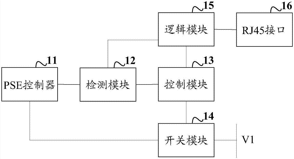
[0039] figure 2A schematic diagram of a PSE structure provided by an embodiment of the present invention, the PSE includes a PSE controller 11 and a first power supply V1, and the PSE also includes a detection module 12, a control module 13, and a switch module 14; wherein,
[0040] The detection module 12 is connected with the PSE controller 11 and the control module 13 respectively, and is used to detect the first output voltage output by the PSE controller 11. If the voltage value of the output voltage changes from a set voltage value to zero, Send the first detection signal to the control module 13;
[0041] The control module 13 is respectively connected to the detection module 12 and the switch module 14, and is used to send a disconnection instruction to the switch module 14 if the first detection signal sent by the detection module 12 is received;
[0042] The switch module 14 is respectively connected to the control module 13, the first power supply V1 and the PSE c...
Embodiment 2
[0047] image 3 A schematic diagram of a PSE structure provided by an embodiment of the present invention, the PSE also includes an RJ45 interface 16 and a logic module 15; wherein,
[0048] The RJ45 interface 16 is connected to the logic module 15 for connecting to a powered device PD;
[0049] The control module 13 is connected to the logic module 15, and is also configured to send a first connection instruction to the logic module 15 if the first detection signal sent by the detection module 12 is received;
[0050] The logic module 15 is connected with the control module 13, the detection module 12 and the RJ45 interface 16 respectively, and is used for connecting the detection module 12 with the RJ45 interface 16 if receiving the first communication instruction sent by the control module 13;
[0051] The detection module 12 is connected to the logic module 15, and is also used to detect whether there is a PD connected to the RJ45 interface 16, and if it exists, send a se...
Embodiment 3
[0059] Figure 4 A schematic diagram of a PSE structure provided by an embodiment of the present invention, the PSE controller 11 is connected to the logic module 15, and is also used to send a second connection instruction to the logic module 15;
[0060] The logic module 15 is connected to the PSE controller 11, and is used to make the PSE controller 11 communicate with the RJ45 interface 16 if the second connection signal sent by the PSE controller 11 is received;
[0061] The PSE controller 11 is also used to supply power to the PD connected to the RJ45 interface 16 .
[0062] Specifically, if the PSE control completes the RJ45 interface 16 connection PD detection and classification according to the POE standard, it sends the second connection instruction to the logic module 15, and the logic module 15 receives the second connection instruction, so that the PSE controller 11 and the RJ45 interface 16 connected, the PSE controller 11 supplies power to the PD.
PUM
 Abstract
Description
Claims
Application Information
 - R&D
- Intellectual Property
- Life Sciences
- Materials
- Tech Scout
- Unparalleled Data Quality
- Higher Quality Content
- 60% Fewer Hallucinations
Browse by: Latest US Patents, China's latest patents, Technical Efficacy Thesaurus, Application Domain, Technology Topic, Popular Technical Reports.
© 2025 PatSnap. All rights reserved.Legal|Privacy policy|Modern Slavery Act Transparency Statement|Sitemap|About US| Contact US: help@patsnap.com